In this blog we will describe Raspberry Pi relay control. Example how to use a PoRelay8 module board. CAN smart relay board PoRelay8 features 8 relay outputs configured over I2C bus. Up to 10 boards can be daisy-chained over the CAN bus for up to 80 additional outputs. In previous blog (8 channel relay module board PoRelay8) we wrote about connecting PoRelay8 relay board to Ethernet I/O controller device over the PoExtBus. The PoRelay8 is an updated version of PoExtBusRe relay board – see the mentioned blog article on advantages.
However, PoRelay8 board can be connected directly to other devices which support communication over I2C protocol. In first part of the blog, we will present an example of connecting single PoRelay8 board directly to Raspberry Pi 3 and in a second part how to drive daisy chained relay modules.
Table of Contents
Table of Contents
Raspberry Pi relay control PoRelay8 – Part 1
Single PoRelay8 relay module connection with Raspberry Pi
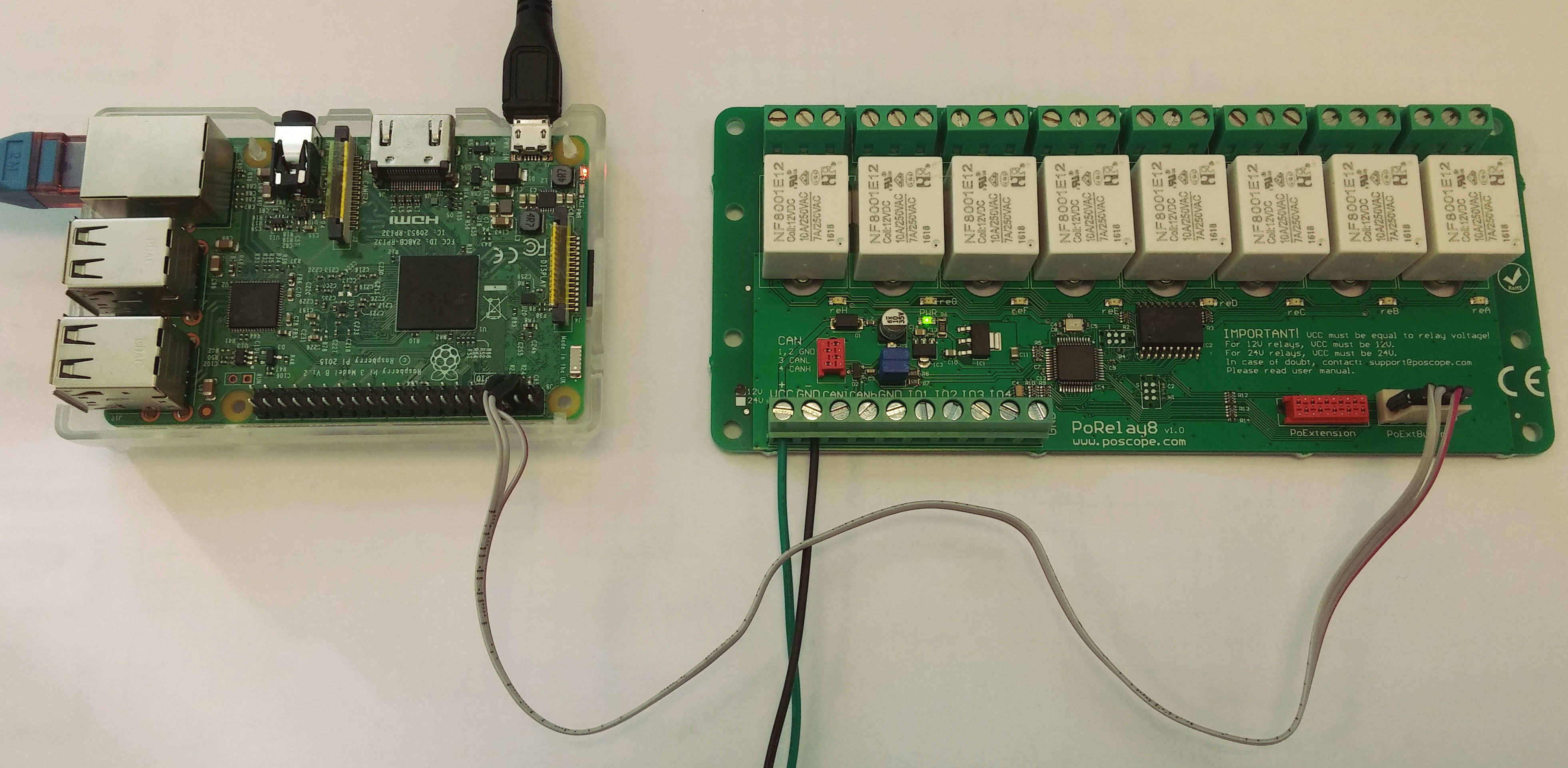
I2C is two wire serial communication and requires two pins (and ground) on Raspberry Pi and PoRelay8 board to be connected together.


For everything to work, pins marked SDA on Raspberry Pi and PoRelay8 must be connected together and same is true for pins SCL and GND.
Before powering up your setup, do not forget that PoRelay board requires a separate 12 V or 24 V power supply (depends on relay type on your board, required power supply is marked on PCB next to screw terminals).

Enabling I2C on Raspberry Pi
I2C bus on Raspberry Pi is disabled by default. It can be enabled with use of raspi-config utility, which is accessed with the following command:
sudo raspi-config
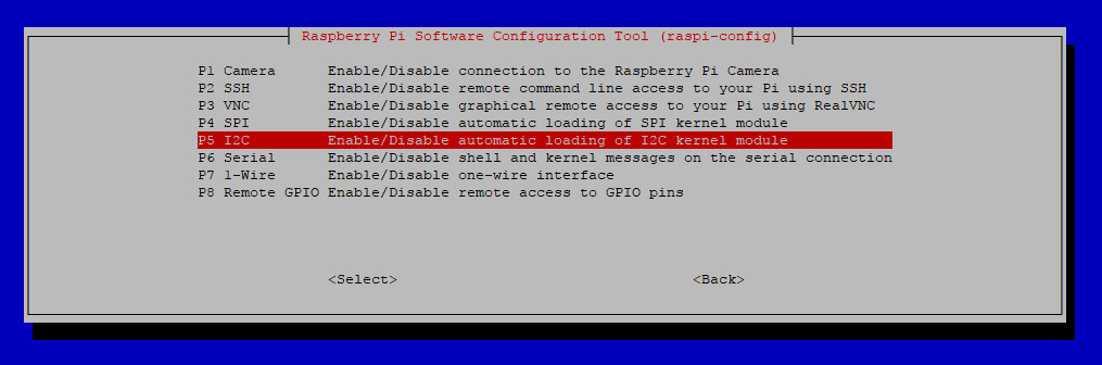
At first screen select option 5 (Interfacing Options) and press enter (picture 4).
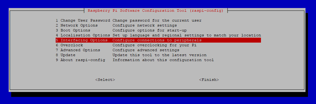
At second screen select option P5 (I2C) and when asked if you want to enable I2C bus, select yes.
Now you can exit raspi-config utility and reboot your Raspberry Pi with command:
sudo reboot
After reboot, I2C is enabled and ready for use.
Discovering devices connected to I2C bus
Raspberry Pi 3 has two I2C buses, numbered 0 and 1. Bus 0 is used for internal applications and it is not available to user.
Each device connected to same I2C bus must have unique 7-bit (or 10-bit) address. To find out your device address you can use i2cdetect command on your Raspberry Pi. In our case two switches are used, -a which will perform scan over all possible addresses and -y 1 to perform scan on correct I2C bus.
sudo i2cdetect -a -y 1
Output should look something like (addresses are represented in hexadecimal format):
0 1 2 3 4 5 6 7 8 9 a b c d e f
00: 00 — — — — — — — — — — — — — — —
10: — — — — — — — — — — — — — — — —
20: — — — — — — — — — — — — — — — —
30: — — — — — — — — — — — — — — — —
40: — — — — — — — — — — — — — — — —
50: — — — — — — — — — — — — — — — —
60: — — — — — — — — — — — — — — — —
70: — — — — — — — — — — — 7b — — — —
i2cdetect tries to contact every possible address and if device is present, it should reply when its address is called. Address 0x00 is general call address to which all devices should respond and can be used if only one slave device is present on the bus.
As we can see, our PoRelay8 board has address 0x7b.
Pigpio library installation and configuration
In this example pigpio library is used for communication over i2c protocol. It provides nice python module for communication with pigpio daemon. Python commands reference can be found on library website. Here are short instructions how to install pigpio library on Raspberry Pi 3:
wget abyz.co.uk/rpi/pigpio/pigpio.zip
unzip pigpio.zip
cd PIGPIO
make
sudo make install
After installation start pigpio daemon with command:
sudo pigpiod
To start daemon at boot time, add this command into /etc/rc.local file.
Setting the outputs on PoRelay8 relay board
Now as we know our PoRelay8 board address and pigpio daemon is running we can use python script to send commands to our relay board as is presented in the following example.
To set PoRelay8 board outputs, 3 bytes of data must be sent to board. First byte is command, which tells PoRelay8 board to turn on or off the outputs. Second byte is actual setting of the outputs, where every bit corresponds to one relay output. Last byte is sum of first and second byte.
Raspberry Pi relay control – Python code example
import pigpio

#Set PoRelay8 board i2c address
DEVICE_ADDRESS = 0x7b

# Connect to Rapberry Pi and open i2c handle to bus 1
pi = pigpio.pi()
bus1 = pi.i2c_open(1, DEVICE_ADDRESS)

# Set Porelay outputs
command = 0x20
outputs = 0x55
checksum = (command + outputs) & 0xFF

request = [ command, outputs, checksum ]

# Send to PoRelay8 board
pi.i2c_write_device(bus1, request)

# Close bus1 handle
pi.i2c_close(bus1)
Output chaser video and code example
import pigpio
import time

# Set PoRelay8 outputs
def i2c_set_outputs( outputs ):

    # Set Porelay outputs
    command = 0x20
    checksum = (command + outputs) & 0xFF

    request = [ command, outputs, checksum ]
    pi.i2c_write_device(bus1, request)

    return

#Set PoRelay8 board i2c address
DEVICE_ADDRESS = 0x7b

# Connect to Rapberry Pi and open i2c handle to bus 1
pi = pigpio.pi()
bus1 = pi.i2c_open(1, DEVICE_ADDRESS)

# Initial output value
output = 0x01

while 1:
    i2c_set_outputs(output)

    # Rotate output
    if ( output < 0x80 ):
        output <<= 1
    else:
        output = 0x01

    # Wait for 200 ms
    time.sleep(0.200)

# Close bus1 handle
pi.i2c_close(bus1)
Relay module for Raspberry Pi – Part 2
First part of this blog, was about connecting and controlling single PoRelay8 board with Raspberry Pi. Raspberry Pi with relay module PoRelay8 communicates over I2C bus. Setup in this example has two limitations. First, I2C bus was developed for communication between devices on same PCB and can be used only by devices position close together. Second, single PoRelay8 board features 8 relay outputs. But what to do if you need more relay outputs? Relay module for Raspberry Pi – Part2 will answer your question.
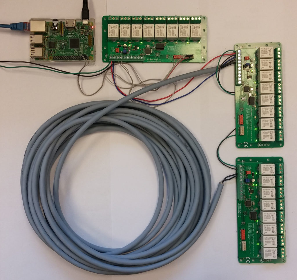
Answer to both limitations is simple: connect together up to 10 PoRelay8 boards over CAN bus in daisy-chain. In this blog we will present example hot to connect 3 PoRelay8 boards to Raspberry Pi and how to communicate with them. Up to 10 boards can be connected to a single master device (Raspberry Pi in our case, but this can be done with any device that supports I2C protocol).
Connecting PoRelay8 boards with CAN bus
For detailed information how to connect first PoRelay board to Raspberry Pi, please look at first part of this blog.
In our setup, first relay board is connected to Raspberry Pi over I2C bus and functions as a bridge. Additional PoRelay boards should be connected to bridge relay board in daisy-chain fashion with use of a CAN bus.
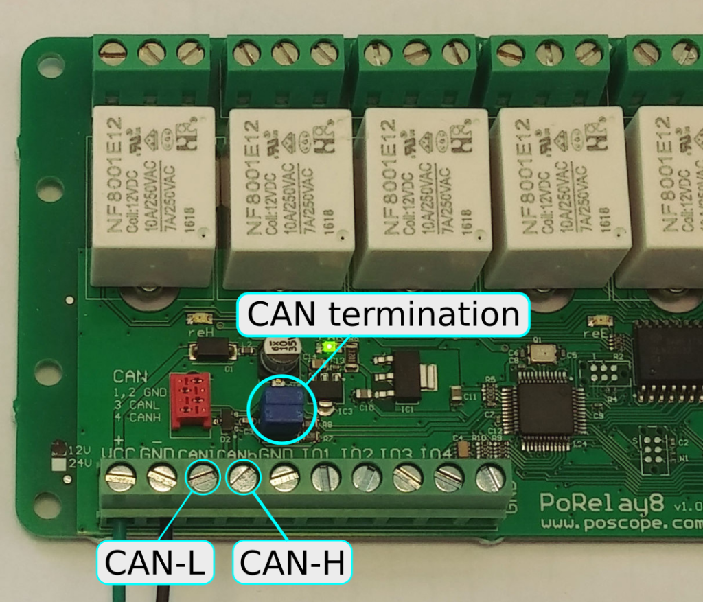
CAN bus connection can be made with flat cable with Micro-MaTch connectors (red connector on the relay board) or with use of screw terminal connectors as our case. All connections (picture 1) marked CAN-L and CAN-H must be connected together in serial fashion. If you want to use long cables, shielded twisted pair cables are recommended.
CAN bus line must be terminated with resistor at both ends. PoRelay boards have termination resistors already integrated. They can be enabled with use of jumper as is shown on picture 1. Watch out for correct jumper orientation. Note that jumpers must be removed on relay boards that are not at the end of the CAN bus (only second board in our case).
Setting the outputs on PoRelay8 boards
Primarily, the PoRelay8 devices were designed to receive data sent over PoExtBus (serial communication protocol used by PoKeys devices for external outputs). PoRelay8 devices also enable the communications over I2C or CAN buses. Communication with bridge board is quite simple as is presented in previous blog. This board can be controlled directly over I2C. Communication to other boards connected to bridge board with CAN bus is a little bit trickier.
In following python example we connected 3 module boards to Raspberry Pi. All communication between Pi and bridge board happens over I2C bus. Bridge board forwards all communication with other boards over CAN bus.
To send data over CAN bus we must start with sending 0x40 value over I2C. This is interpreted as send over CAN command. Follows CAN message ID, which consist of two bytes: 0x01 and 0x08. Next byte is number of data bytes we want to send, followed by all data bytes. Last byte is checksum of all sent bytes.
However, we can simply read the data received from CAN bus. It starts with writing 0x41 byte to I2C bus and reading from I2C expected number of received bytes from CAN bus. First byte should have value 0x1A, as marker that we received the data and is valid.
In our case and python example, we have 2 PoRelay boards connected to bridge board over CAN. At beginning we know I2C address of the bridge board and we can set its outputs simply as we described in the first part. Now we have to find out addresses of two boards connected to bridge. This can be done by issuing CAN identify command. To do this, we write to I2C bus next bytes:
| Send over CAN | Data length | CAN message ID | Data | Checksum | |
| 0x40 | 0x01 | 0x08 | 0x01 | 0x10 | 0x5A |
In this case, data part with value 0x10 is interpreted as request for identification. Each board connected to bridge will respond with 12 bytes long CAN message containing information about it. Received bytes from 8 to 12 represent boards unique address, that must be used when setting outputs on desired board.
To set the outputs of desired board connected over CAN bus, following sequence must be written to I2C:
| Send over CAN | Data length | CAN message ID | Data | Checksum | ||||||
| Set outputs | Board address | Outputs | ||||||||
| 0x40 | 0x01 | 0x08 | 0x06 | 0x20 | 0xXX | 0xXX | 0xXX | 0xXX | 0x55 | 0xXX |
This will set outputs targeted board to pattern 01010101. Checksum is sum of all sent bytes masked with 0xFF, as its value must not be greater than 255.
Following python example will do next:
- Identify bridge board and write out boards address and firmware version
- Set outputs of bridge board to 0x55
- Identify all boards connected to can bus and print out their addresses
- Set outputs of every board to lowest byte of its address
Do not forget, for this example to work, you must have pigpio library installed on your Raspberry Pi and daemon running.
Relay module for Raspberry Pi – Python example
import struct
import time
import pigpio
import random

############################
# Read data from CAN
############################
def CAN_read():

    request = [ 0x41 ] # Read from CAN command
    pi.i2c_write_device(h, request)
    (count, response) = pi.i2c_read_device(h, 13)

    # Check if received data is OK
    if ( response[0] == 0x1A ):
        return response
    else:
        return 0

#############################
# CAN identify
#############################
def CAN_identify():

    command = [ 0x40 ] # Send over CAN
    CAN_ID = [ 0x08, 0x01 ] # CAN message ID
    data = [ 0x10 ] # Identify command
    data_length = [ len(data) ]

    request = command + data_length + CAN_ID + data
    request.append( sum(request) & 0xFF ) # append checksum

    pi.i2c_write_device(h, request)
    (count, response) = pi.i2c_read_device(h, 1)

    print("Response after Identify command:")
    print(response[0])

    # Wait for 400 ms for replays from all boards
    time.sleep(.400)

    device_num = 1
    found_devices = []
    while True:
        response = CAN_read()

        if response:
            found_devices.append( list(response[8:12]) )

            (device_id,) = struct.unpack_from("I", response[8:12], 0)
            print( 'Device {} ID: {:02x}'.format(device_num, device_id) )
        else:
            break

        device_num += 1

    return found_devices

#############################
# Set outputs on CAN board
#############################
def CAN_set_outputs(board_id, output):

    command1 = [ 0x40 ] # Send over CAN
    command2 = [ 0x20 ] # Set outputs command
    CAN_ID = [ 0x08, 0x01 ]
    data = [ output ] # Identify command
    data_length = [ len(command2) + len(data) + len(board_id) ]

    request = command1 + data_length + CAN_ID + command2 + board_id + data
    request.append( sum(request) & 0xFF ) # append checksum

    pi.i2c_write_device(h, request)

    return

#############################
# Main program
#############################

pi = pigpio.pi()

DEVICE_ADDRESS = 0x7b # 7 bit I2C address of relay board

h = pi.i2c_open(1, DEVICE_ADDRESS)

request = [ 0x10 ] # Identify board command, to which bridge beard will respond
pi.i2c_write_device(h, request) # Send first command
(count, response) = pi.i2c_read_device(h, 9) # Read bridge board response (9 bytes)

# Print bridge board address (in hex format) and version
print( 'Version: {}.{}'.format(response[3], response[4]) ) #
(device_id,) = struct.unpack_from("I", response, 5)
print( 'Bridge Device ID: {:02x}'.format(device_id) )

# Set outputs on Bridge relay board
outputs = 0x22
request = [ 0x20, outputs, (outputs + 0x20) & 0xFF]
pi.i2c_write_device(h, request)

# Identify devices connected to CAN bus
can_boards = CAN_identify()

# CAN Set outputs
for device in can_boards:
    CAN_set_outputs(device, device[0]);

pi.i2c_close(h)
For 48V version of programmable relay click on the link.
You are welcome to read also our other articles.
Information about stepper motor, complete explanation about stepper motor driver.
Please check also our latest blog posts and products. It can help you to improve your machines or get some ideas on how to even make them better.
- PoKeys57CNC – USB CNC CONTROLLER
- Homing sensor
- Torch height controller – THC
- Bipolar stepper motor driver – PoStep25-256
- PCB tester – PoStep25-256
- 4th axis for CNC
- Introduction to CNC hardware – electronics
- Plasma cutting equipment
- What is CNC plasma cutting
- CNC plasma floating head
- Plasma cutter troubleshooting guide
Related Posts