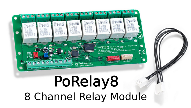
8 channel programmable smart relay board PoRelay8 allows expanding the number of outputs of the PoKeys device by using the PoExtBus. It features 8 relay outputs. Up to 10 boards can be daisy-chained over the CAN bus for up to 80 additional outputs. CAN (Controller Area Network) bus is a robust bus standard initially designed for automotive use to allow devices to communicate with each other.
Table of Contents
The CAN Relay – PoRelay8 smart relay board replaces PoExtBusRe IO port expansion devices. The PoRelay8 was designed to offer the improved functionality and robustness in the same form factor as a favourite relay board PoExtBusRe. The new PoRelay8 can be daisy chained with cable distances of more than 10 meters!
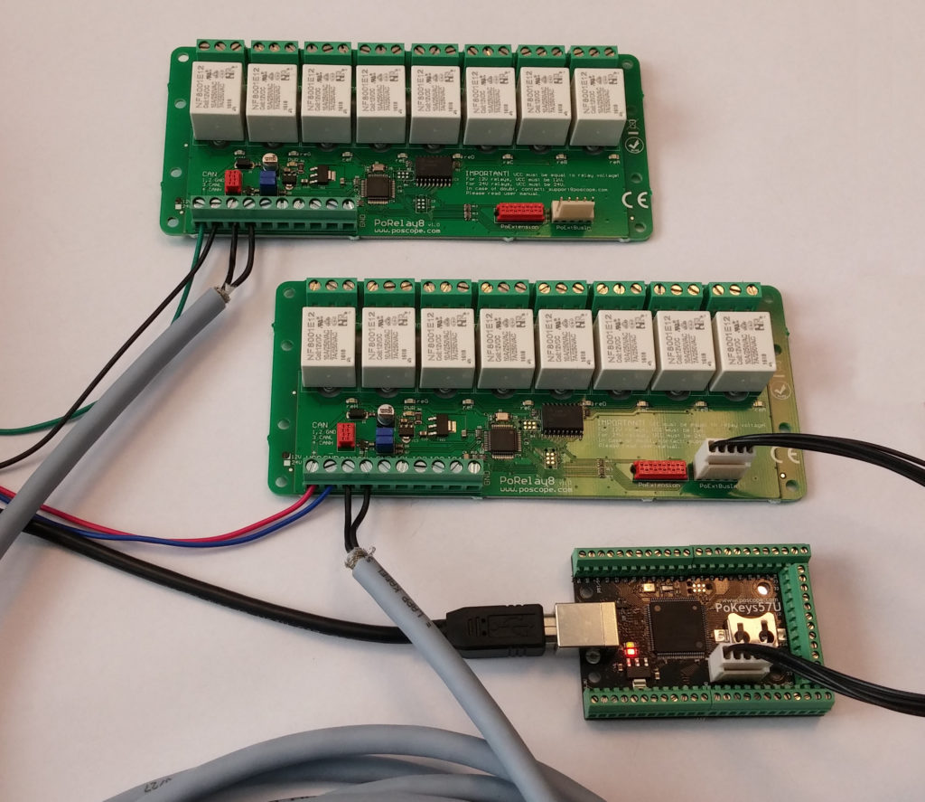
Connection two Porelay8 programmable smart relay boards to PoKeys57U
In this example we will show how to connect and use two programmable smart relay boards, where first is connected to USB I/O controller PoKeys57 device and second board is connected to first with long cable using CAN bus. There is no extra programming needed since CAN bus is internal
 Connecting PoRelay8 boards to PoKeys device
PoRelay8 board requires 12V or 24V external power supply, depending on relay type. Please use correct power supply for powering your board. Required power supply is marked on bottom left corner of the PoRelay8 boards or check relay type.
The first 8 channel relay module board PoRelay8 must be connected directly to PoKeys device with the supplied 5 wire PoExtBus cable. This board functions as a bridge. All other boards are daisy-chained to bridge board with the use of a CAN bus. If PoRelay8 boards are placed far apart, use of twisted pair cable is recommended, which you can connect to screw terminals on the boards. For shorter distances, you can choose flat cable with Micro-MaTch, a red 4-pin connector.
CAN bus must be terminated with 2 resistors at beginning and at the end of the bus (but not on devices in between). Termination resistors are already integrated on PoRelay8 boards and can be enabled with use of jumpers. Watch out for correct jumper orientation!
1-  Connection to PoKeys device, 2- Relay connectors, 3-Micro-MaTch connector for CAN bus, 4- CAN bus termination resistors jumpers, 5- Screw terminals for power supply, 6- Screw terminals for CAN bus
8 channel smart relay module PoRelay8 – daisy chain setup
Before use, PoRelay8 board sequence ID-s must be configured in PoKeys application. This can be done by starting application, connecting to PoKeys device, then opening Peripherals menu and selecting PoExtBus smart … option.
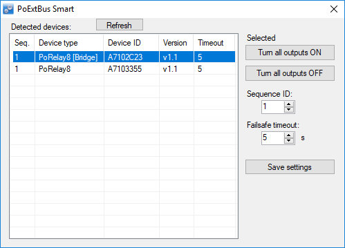
In PoExtBus Smart window all detected PoRelay8 boards are listed. Board, connected directly to PoKeys is marked as “Bridge”. All other boards are listed bellow and can be identified with turning all outputs ON and OFF. After board has been identified, Sequence ID for the board must be selected and fail-safe timeout for each board can be changed.
Sequence ID determines which part of the PoExtBus data is used by the PoRelay8 device (displayed as x number in the label ‘Device x’ in the PoExtBus settings dialog, shown below). The device that takes the first position data has the sequence ID of 1, the second has sequence ID 2 etc. Fail-safe timeout function is to turn off all relays if communication with PoKeys device is lost for more than timeout setting. Timeout must be longer than 1 second. If set to 0, timeout is disabled. After settings have been modified, do not forget to save them by clicking Save settings button.
When everything has been configured, configuration can be tested by opening Peripherals menu ans selecting PoExtBus … option.
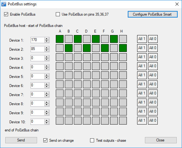
Before testing, check that Enable PoExtBus is selected. With left click on grey square, output is turned ON and with right click on green square, turned OFF. To send output values to the devices, click on the send button. If immediate change of outputs is desired, option send on change can be selected. Test output – chase option will automatically turned ON and OFF all outputs from first to last.
Standalone use – programmable smart relay using PoBlocks application
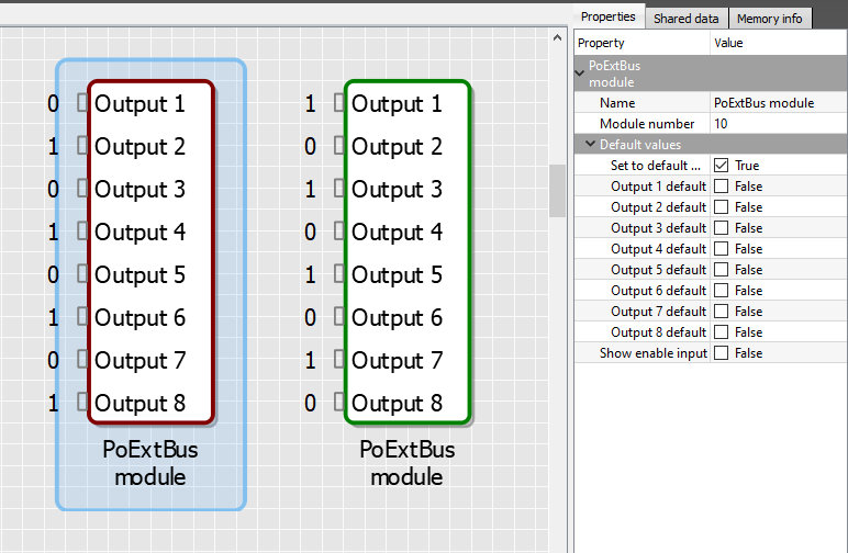
In PoBlocks, PoExtBus module can be found in the IO menu. In our case, two modules were selected, as we have two Porelay8 boards. To each module module number must be assigned. Module numbers are in reverse order than Sequence IDs of boards in PoKeys configurator, so care must be taken to select right module numbers.
In our case, first board has sequence ID 1 and corresponding module number 10 must be selected. For second board with sequence ID 2, module number 9 must be selected.
Now outputs can be set by right clicking on the output and selecting desired output value. After all values has been set, Check and Transfer is clicked and if everything is alright, after clicking RUN outputs on PoRelay8 boards are set.
Example code using different programming languages
C# example driving 8 channel relay module
using System;
using System.Collections.Generic;
using System.Linq;
using System.Text;
using System.Threading.Tasks;

namespace PoKeys_PoRelay8
{
    class Program
    {
        private static PoKeysDevice_DLL.PoKeysDevice device = new PoKeysDevice_DLL.PoKeysDevice();

        static void Main()
        {
            byte[] dataOut = new byte[10];

            // Find all PoKeys devices
            int devNum = device.EnumerateDevices();

            // Connect to the device with serial number 36860
            // Replace serial number with serial number of your device!
            if (device.ConnectToDevice(36860, 0) == false)
            {
                // Error connecting to the device
                Console.WriteLine("Error connecting to the device!");
                Console.WriteLine("Press any key to exit ...");
                Console.ReadKey();
                System.Environment.Exit(1);
            }
            // Turn ON relays ACEG on board 1 and CDGH on board 2
            // Devices are in reverse order and indexed from 0!!!
            dataOut[9] = 0xAA;
            dataOut[8] = 0x33;

	    // Send new output values to the device
            device.AuxilaryBusSetData(1, dataOut);
        }
    }
}
C example
#include <stdio.h>
#include <windows.h>
#include "PoKeysLib.h"

int main()
{
	int dn;
	sPoKeysDevice* device;

	// Enumerate USB devices. Returns number of USB devices detected.
	dn = PK_EnumerateUSBDevices();
	printf("Devices found: %i \n", dn );

	// Connect to the device with serial number 36860
    	// Replace serial number with serial number of your device!
	device = PK_ConnectToDeviceWSerial(36860, 0);

	// # Error connecting to the device
	if (device == NULL)
	{
		return 0;
	}

	// Turn ON relays ACEG on board 1 and CDGH on board 2
	device->PoExtBusData[9] = 0xAA;
	device->PoExtBusData[8] = 0x33;

	// Send to PoKeys57
	PK_PoExtBusSet(device);

	return 0;
}
Python example
import sys
import time

from PoKeys import *

# Load PoKeysLib dll library and list all PoKeys devices detected
device = PoKeysDevice("PoKeysLib.dll")
print("List of detected devices:")
device.ShowAllDevices()

# Connect to the device with serial number 36860 and do not search for ethernet devices
# Replace serial number with serial number of your device!
if device.PK_ConnectToDeviceWSerial(36860) != 0:
	# Error connecting to the device
	print("Device not found, quitting!")
	sys.exit(0)

# Get current configuration
device.PK_PoExtBusGet()

# Turn ON relays ACEG on board 1 and CDGH on board 2
# Devices are in reverse order and indexed from 0!!!
device.device.contents.PoExtBusData[9] = 0xAA
device.device.contents.PoExtBusData[8] = 0x33

# Send to PoKeys57
device.PK_PoExtBusSet()
Additional information on the PoExtBus Smart protocol is provided in the 8-channel relay module PoRelay8 user manual, accessible via the Downloads section.
Please check also our other blog articles, where we describe examples using the PoRelay8 relay module with Arduino and Raspberry Pi.
More about
More information about pokeys products and blog posts, which can help you to upgrade your machine or get some ideas:
- Stepper motor driver (complete explanation)
- Homing sensor – PoHome1IRNPN
- plasma voltage divider
- Bipolar stepper motor driver – PoStep25-256
- PCB tester – PoStep 25-256
- 4th axis for CNC
- Introduction to CNC hardware – electronics
- plasma cutting equipment
- what is CNC plasma cutting
- What is CNC plasma floating head
- plasma cutter troubleshooting guide
Related Posts