Do you want to better understand the stepper motors, stepper motor driver and how they work? What is the difference between RMS and PEAK current? We want to present to you the advantages of the new generation of stepper motor drivers and the superior performance that they offer.
Table of Contents
Introduction to stepper motors and drivers
We previously wrote about stepper motor drivers and how they work. The focus of this article is to further explain the important differences between older and newer stepper drivers and what advantages do they bring. The stepper motor is already about 100 year old concept of a simple 2 phase motor. The motor is designed to be able to rotate the predefined angle when excited the right way.
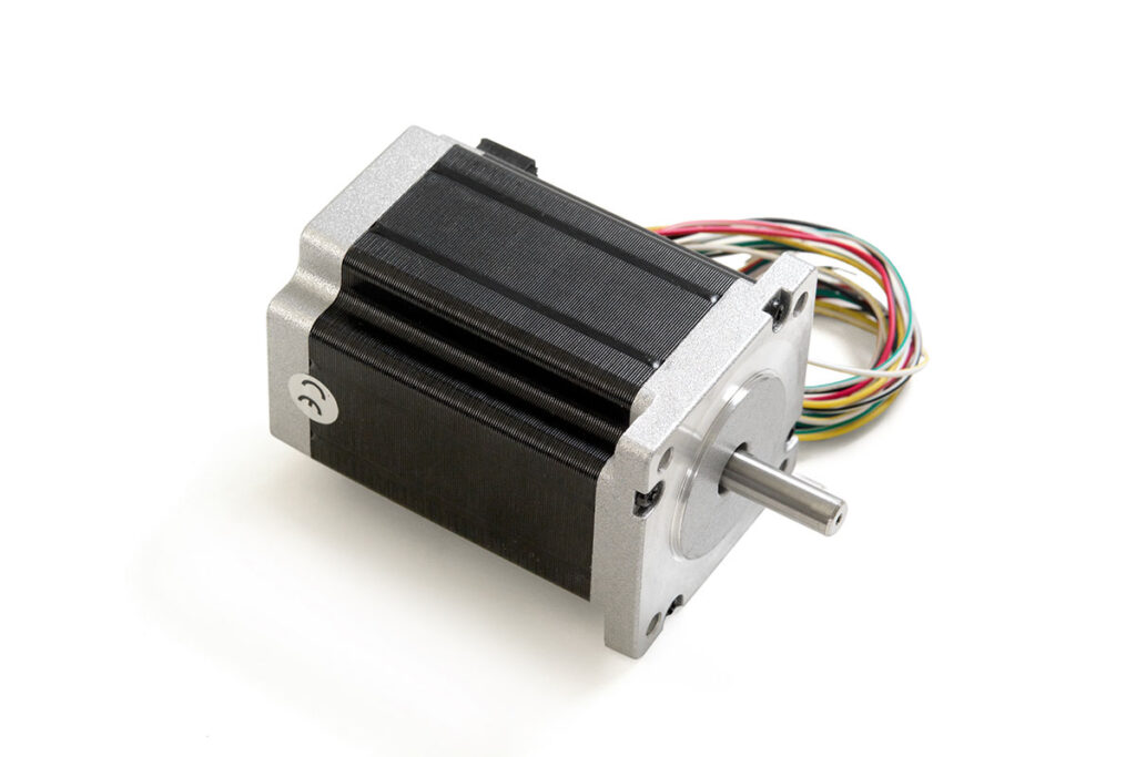
Stepper motors are nowadays used in precision control, automation, cnc machines, robots, etc. We are still using them because of the low price and the simplicity that they offer. The complex servo systems are surely better. But the wiring, setting up the control as well as complex tuning of the system along with the high price are often to big of a step for the simpler systems.
The stepper motors require only the connection of the driver to the motor and power supply. The control of the driver is step and direction control, which is very common and simple to understand. Step signal gives the required pulses for the driver that represent how many steps to turn the motor and the direction signal determines the direction, in which the motor is turning.
RMS or PEAK stepper motor current & stepper motor voltage
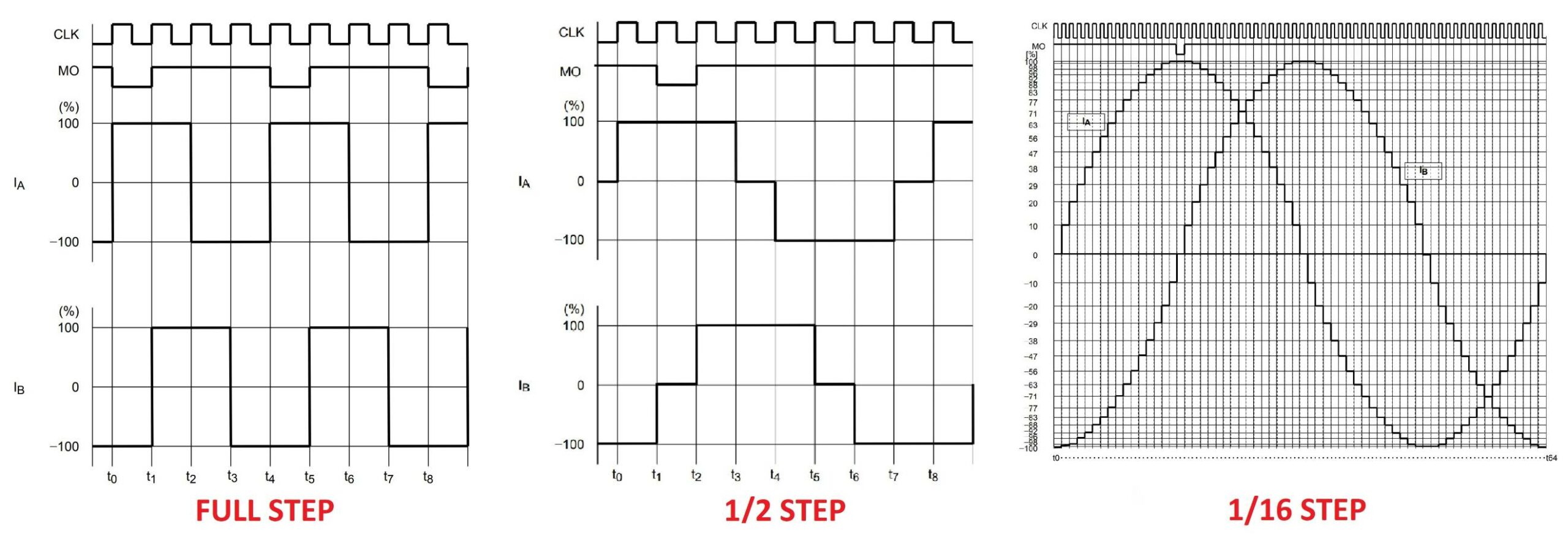
First we have to understand the importance of microstepping. The 2 phase stepper motors have two coils, and for turning the motor you have to excite the two coils in special order. Stepper motors have usually around 200 steps per revolution. If your driver is in full step mode, with 200 pulses on the step pin the motor will make a full turn.
If you want to further divide the angular resolution or you would like to achieve smoother motion you can divide full steps into smaller microsteps. That means that with two coils, you have to partially excite them to achieve smaller physical angular movement of the motor shaft. That angular movement can be less than the full step (less than 1.8° with 200 steps stepper motor).
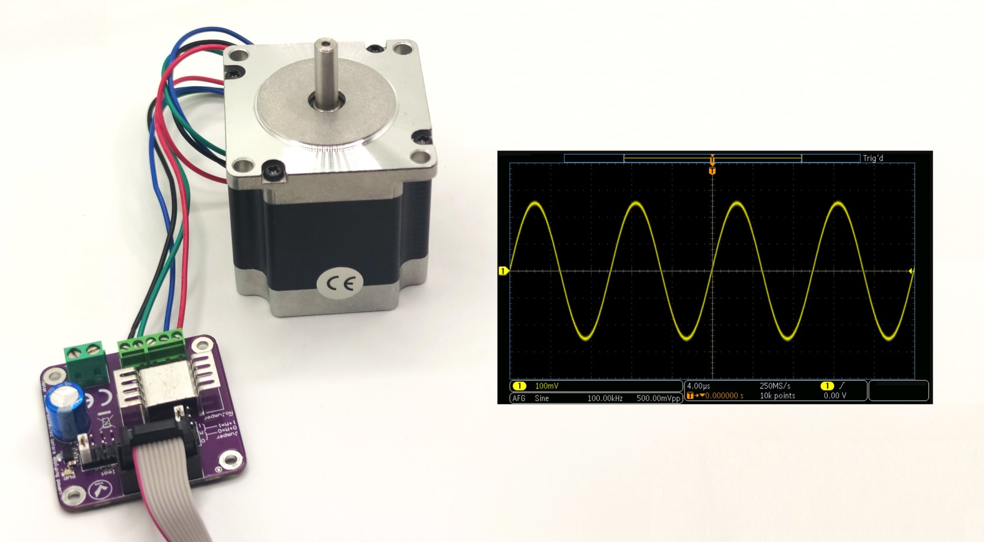
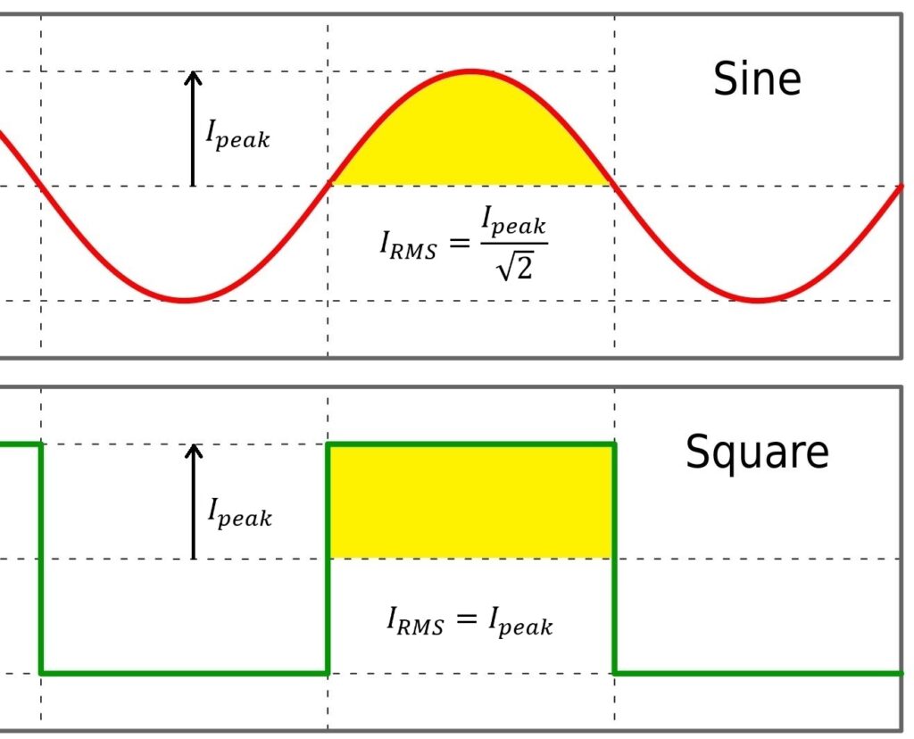
The current in the coils starts to look like sine wave the further we divide the step into microsteps. The effective current of the sine wave in not the same as the current in the full step mode. That is of course if the peak current stays the same. In the graph, we can see the square wave as well as the sine wave. The yellow area under the graph represents the charge in time interval.
That said, the RMS or the effective values are not the same with full steps or the maximum microstepping. For microstepping (with sine wave), the peak value of the current has to be higher. To be precise, the peak current has to be 1.41 times higher (square root of 2).
Microstepping is not what it used to be
Microstepping in the newest generation of the stepper motor drivers is not the same as before. In older drivers, stepper motor current was directly and instantly toggled as soon as the step pulses were detected. The driver immediately set the current according to the microstep setting of the driver. The new generation of the drivers does not have that direct connection anymore.
The microstepping setting is now only for the input step pulses interpretation. The driver drives the motor as if it was set for 256 microstep settings. The microstep setting is only for the input STEP signal since most of the controllers can not generate 256 microstep STEP signal for the fast motor speeds.
The benefit of that is smoother motion and lower vibration. If the older drivers were set for the low microstep settings (full or 1/2 etc.) the vibrations were very high in the lower speed range of the motor. With 256 microstep interpolation the stepper motor current is much smoother and overall performance significantly improved.
Measuring stepper motor current
To measure current, one can use ordinary multimeter. But for observing the waveform of the current and study the control characteristics of the driver, oscilloscope current probe is needed. We developed the particular probe for reliable and accurate measurements. We wanted to test and make sure, that our stepper motor driver has the best performance possible.
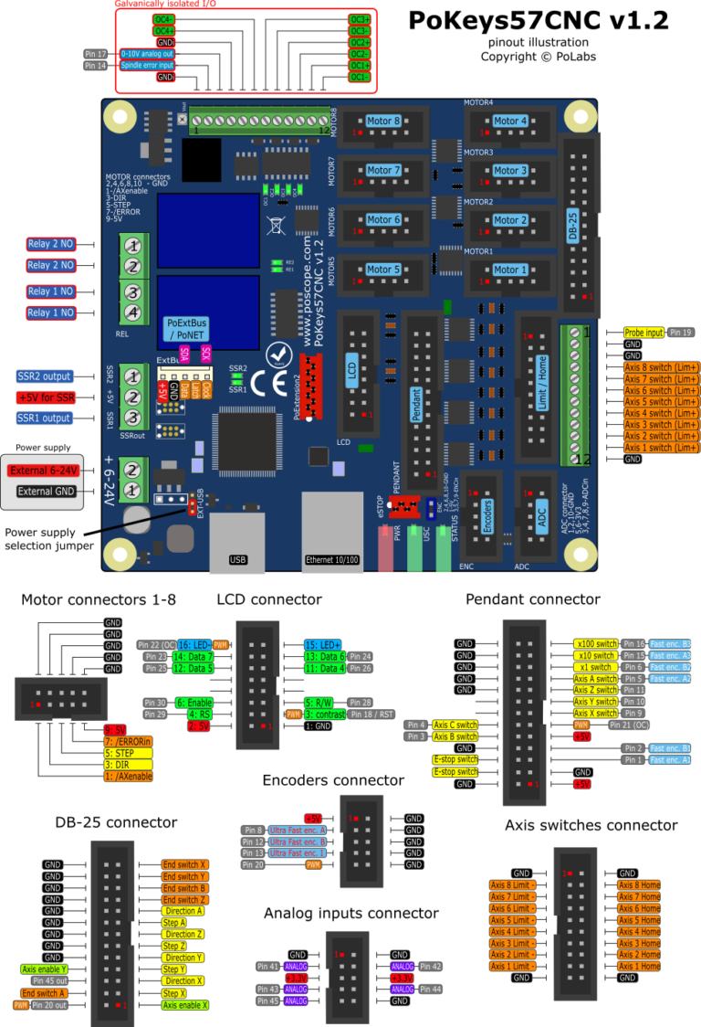
The probe is connected in series with one of the coils of the stepper motor. That enables us to observe the current in one of the phases. The probe is then plugged into our oscilloscope and with that, setup for measuring current is complete. For control of the driver, we used PoKeys57CNC controller with motion engine from our app.
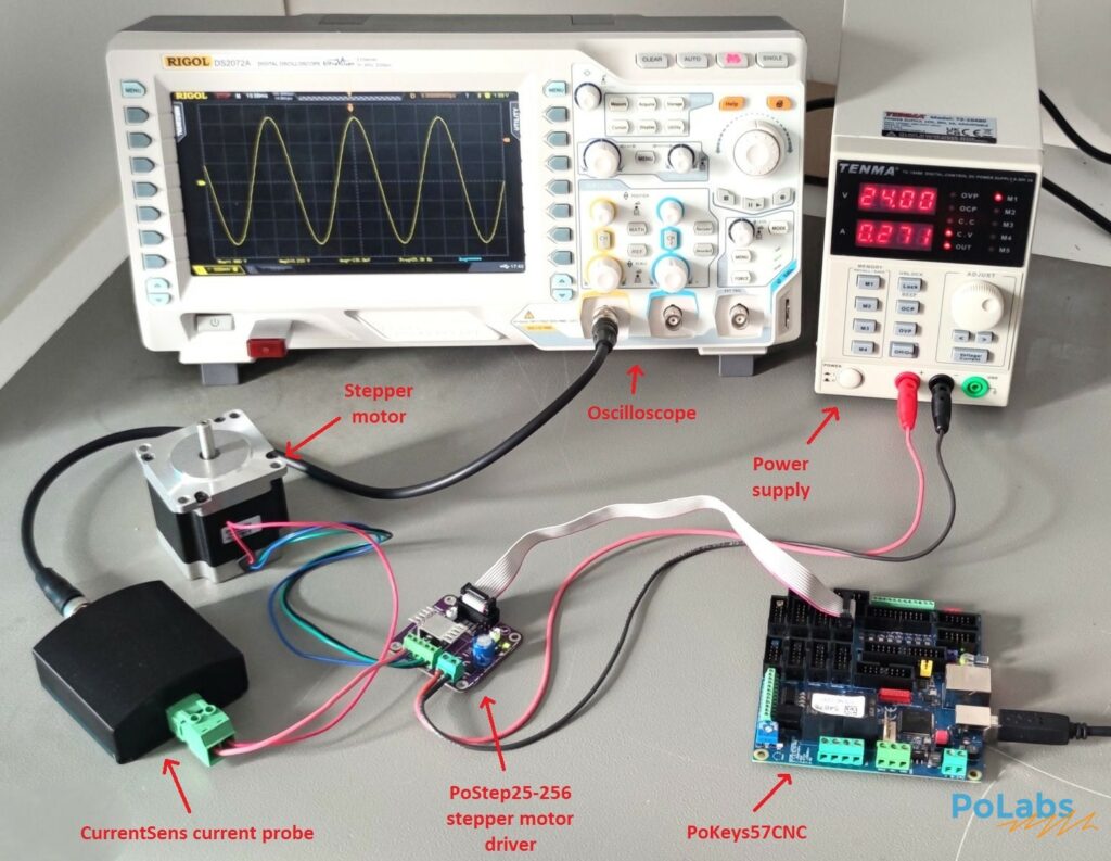
The next step is to set up the oscilloscope for making the measurements. The expected voltage from the probe is below 500 mV so the channel has to be set up that way. The reference on our probe can also be set up with 0V reference voltage for zero current as explained in the CurrentSens manual. We will use 5A RMS current probe so the 125mV represents 1A of current. With that we can directly know the current from oscilloscope measurement.
Stepper motor current with OLD and NEW drivers
The clean current waveform is the main reason for smooth and silent stepper motor operation. Any artifact in the waveform of the current adds to higher vibration and noise. The critical parts of the waveforms are zero cross and precise current regulation.
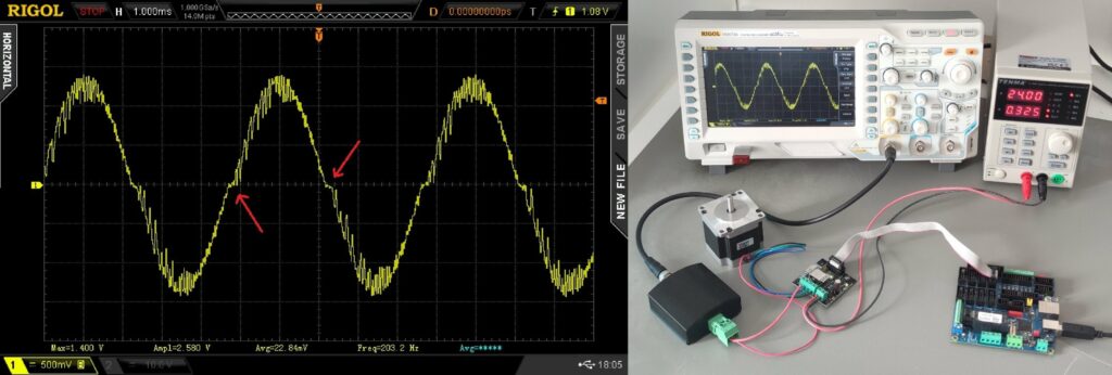
The tests of the old driver (PoStep25-32) also revealed excessive vibration at different speeds. Vibrations were present at standstill as well if the stepper motor was stopped in certain positions at different microstep values. The test was repeated with newer stepper motor driver with same conditions.
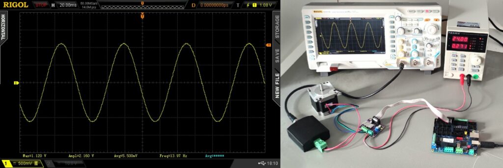
The performance of our new bipolar stepper motor driver was much better with quiet and smooth operation. The motion was smooth and without jerk. The performance of the stepper motor was directly related to the current of the motor. Our much more powerful stepper motor driver also has advanced control algorithms to provide smooth current and superior performance in your stepper motor application.
Advantages of new stepper motor drivers
New stepper motor drivers have a lot of advantages compared to older ones:
- Higher microstepping resolution – they offer much higher microstepping resolution compared to older models which makes the motion smoother with less vibrations
- Higher current capability with less heating – newer models offer higher currents for bigger motors without need for excessive cooling
- Advanced control features – they offer control features such as stall detection, more precise control and better performance
- Quieter operation – because of advanced current control and microstepping they are much quieter
- More compact and efficient design – they offer much simpler and smaller designs for easier integration
Although older models are still available on the market, for new projects and use cases the new drivers are much more appropriate and will offer reliable operation and loger lifetime.
About
Polabs is developing and manufacturing electronic products for many different areas and needs and also developed some machines to make work easier, more productive, and higher quality. Below, here you can find some latest blog posts and products:
Current measurement with oscilloscope

