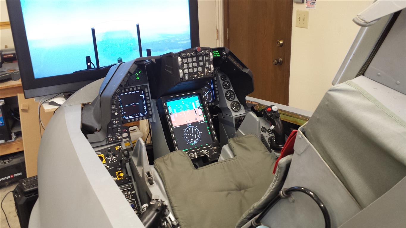
PoStepVID6606 is a new product in our series of stepper motor drivers. 8-channel miniature stepper motor driver based on VID6606 integrated circuit. The device is a perfect choice for making a flight simulator where several instruments are included on the control panel. The device is suitable for use with PoKeys, but also without restrictions on any other microcontroller board.
Here is a quick explanation and some hints for fast integration PoStep VID6606 in to your project.
Table of Contents
Feature of the stepper motor driver based on VID6606
- 8-channel stepper motor outputs
- up to 35 mA current per channel
- up to 125 kHz step signal frequency with PoKeys
- Serial Step/Direction protocol
- Screw terminals for motor wires
- Backlight power distribution
PoStepVID6606 pinout and connection
The device has practically screw terminals for power supply voltage and motor wires. Motor terminals are also available at 8-pin Micro-MaTch connector where a backlight power supply voltage is an additional option on connector’s pins. For serial communication there is a Micro-MaTch connector with 3 digital and one common GND signal, to connect to a microcontroller board. For power supply the device is using DC voltage from 12 V to 24 V. The maximum power consumption will not exceed 3 Watts.
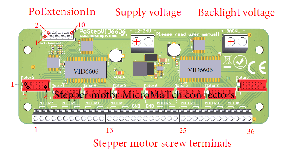
The backlight we can power using motor Micro-MaTch pins 1,3 and 2,4. However, the backlight voltage on those pins is just distributed voltage from the backlight supply connector and can be AC or DC with a current maximum 0.5 A.
Driving with PoKeys57- flight simulator
PoStepVID6606 is shipped with the cable attached to the PoExtensionIn. To use the device together with PoKeys57E or PoKeys57U, connect the flat cable to the appropriate pins of the PoKeys57E/57U device as shown on Picture 2. PoStepVID6606 uses 3 input pins and GND to communicate with the master device.
| PoExtensionIn | Pin describtion | PoKeys57U | PoKeys57E |
| 2 | Ground (GND) | GND | GND |
| 8 | SER (Data) | 23 | 9 |
| 9 | SCK (Clock) | 25 | 11 |
| 10 | RCK (Latch) | 26 | 51 |
Picture 2: PoExtensionIn connector pinout and associated Pokeys57U/E pins
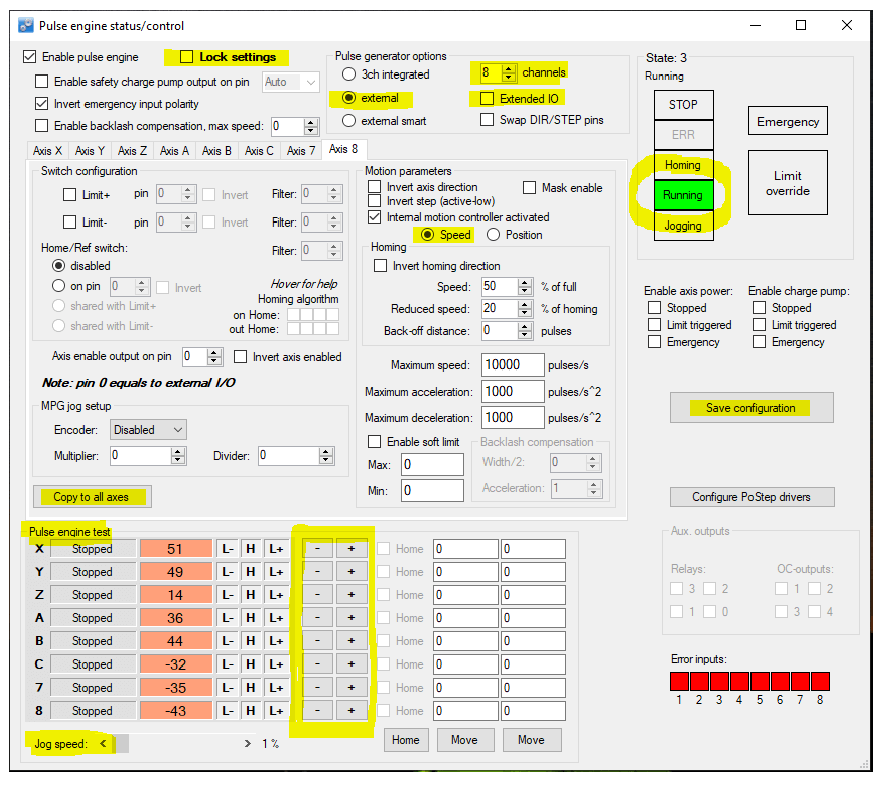
First run the PoKeys application, open “Pulse engine” settings and follow these steps:
- Release the settings lock by clicking ‘Lock settings’. The dialog will be asking you whether you want to load default settings. Confirm with ‘Yes’
- Select ‘External’ in Pulse engine generator options and uncheck the ‘Extended IO’ check box
- Select 8 channels in Pulse engine generator options
- Under ‘Motions parameter’ choose ‘Speed’
- Click ‘Copy to all axes’
- Click ‘Save configuration’
Then test the operation of the device. Switch Pulse engine into ‘Running’ mode (by clicking ‘Running’ button) and use the +/-jogging buttons for the target axis in ‘Pulse engine test’ section. The default jog speed is 1 % of the maximum speed use the slider at the bottom to adjust the jogging speed.
Serial communication protocol description
A single VID6606 chip has the ability to drive up to 4 stepper motors. In that case, we would need 8 input signals, four for step signals and four for directions. As you probably guessed, with 8 channels the number of inputs increases twice. Therefore, PoStepVID6606 reduces 16 input signals to only 3 thanks to the serial-parallel conversion circuit. The communication between PoStepVID6606 and the master device is based on a synchronous unidirectional protocol using clock, data and latch signal.
Even more, PoStepVID6606’s digital TTL data input levels are +3.3V and +5V compatible. The serial data length is 16-bit and contains step and direction signal for 8 stepper motor driver VID6606 inputs. Data is organized as you can see on Picture 4.
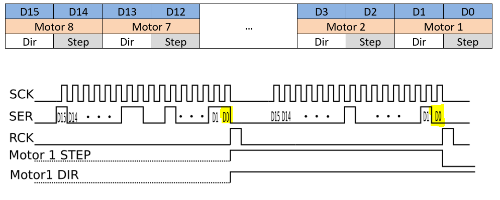
The most significant bit (MSb) must be sent first! Step/Direction outputs are latched at the rising edge of the RCK signal. Driver VID6606 can operate with step signals frequency up to 1MHz. At least two 16-bit data packages must be sent to generate a single-step pulse signal.
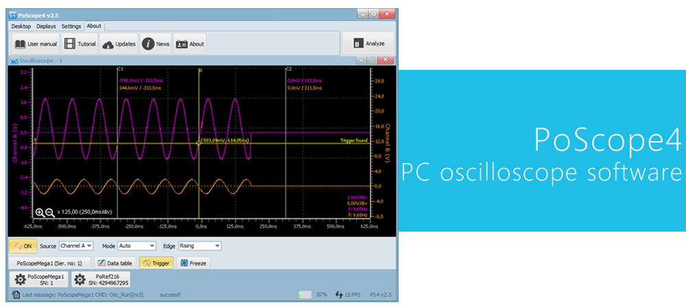
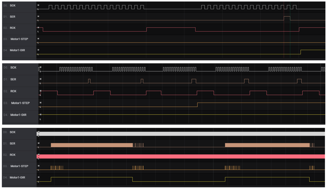
However, the PoStepVID6606 serial protocol allows different approaches to generating step/direction signals. One of them is sending ‘0’ in constant time intervals and sending ‘1’ when step pulse or reverse direction is required. That kind of approach is used in the PoKeys application (Picture 5)
Information about stepper motor driver, complete explanation about stepper motor driver.
Please check also our latest blog posts and products. It can help you to improve your machines or get some ideas on how to even make them better.
- Bipolar stepper motor driver – PoStep25-256
- Torch height controller – THC
- Homing sensor
- PoKeys57CNC
- PCB tester – PoStep25-256
- 4th axis for CNC
- Introduction to CNC hardware – electronics
- plasma cutting equipment
- What is CNC plasma cutting
- CNC plasma floating head
- plasma cutter troubleshooting guide
Related Posts