Are you having problems with reliability of your machine or are you planning on making a DIY CNC and want to maket the electornics as reliable as possible? Here are some tips for CNC wiring your machine..
CNC wiring introduction
CNC machines usually have separate compartment or cabinet for all the electronics. That way they are protected from chips and all the debris from cutting. There are few general rules that should be followed when designing and wiring the electrical cabinet and all the electronics within.
By following the rules and guides the CNC wiring will be much more reliable and electronics will last longer. Also the signals will be much more reliable, especially with critical signals like end switches and probing. Implementing some simple concepts, you will have much better performing cnc machine and processes.
Electrical components
CNC electronics usually consists of following components:
- CNC controller such as our Mach4 CNC controller. It controlls the machine, all the motion and output and input signals. It is sensitive piece of electronics that should be well protected physically as well as electronicalls from EMI and other interference.
- Motor drivers that could be stepper motor drivers or AC servo drivers. They accept the sensitive digital signals from the CNC controller on one side and have high power part with motor circuitry and motor and power wires on other side.
- Power supply that usually convert high AC voltage power to lower voltage like 12 V or 24 V for signals and circuitry.
- VFD (variable frequency drive) for spindle in case of the CNC router/mill. It drives the spindle motor with variable RPM. It is mainly high voltage part of electronics with digital (and analog) signals for control of the RPM and direction.
- Plasma source for CNC plasma cutters that has the plasma torch connected for cutting of the sheet metal. It emits a lot of electrical noise and should be kept outside the electronics cabinet with galvanic isolation between it and other parts of electronics.
- Relays such as our programmable smart relay and other high power switching parts of electronics for control of various peripheral devices.
As indicated, there are more and less sensitive electronics components and signals in the CNC control cabinet. That has to be considered and taken into account for layout of the cabinet and all the CNC wiring. More dirty signals have higher currents flowind through them or high voltage spikes. Also all rapidly changing values of current or voltage cause the noise emissions that can interfere with other sensitive signals and parts of electronics.
Grounding, cable shielding and interference
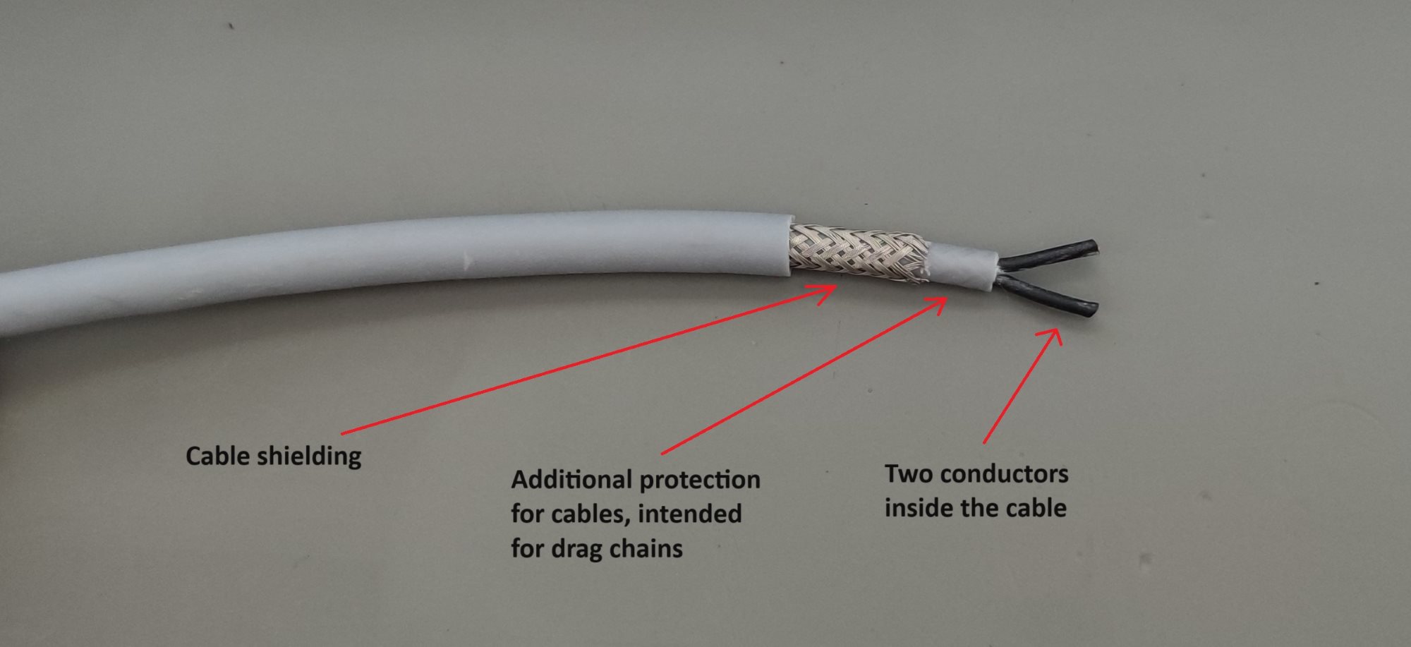
It is recommended that all the “dirty” signals have shielded cables. Shielding in the cable is layer of wire mesh around all the conductors in the cable. It protects the cables within from outside interference as well as contain the interference of the cables themself. It is not effective on its own at all, so special care has to be taken if you want to shield cables properly.
Cable shielding is closely related to proper grounding in the electrical cabinet. Ground wire should be wired to the electrical cabinet from the main electrical plug. The ground wire should then be distributed throughout the cabinet in the star formation. All the grounded components should be wired to the one common ground terminal.
Star configuration ensures that there are no loops formed in the grounding scheme of the electrical cabinet. Loops can cause different electrical potentials and voltages on the ground leads. They also act as antennas and pick up the electromagnetic energy and cause noise in the signals.
All the shielded cables should have the shielding grounded only on one side, preferrably at the connection to the electrical cabinet. That is important for all the cables going out from the electrical cabinet, from 3 phase spindle power cable, to all the motor cables and end switch cables. It is recommended for all the cables and wiring, especially in case of the long cables. The proper shielding will ensure integrity of the signals and much higher reliability of the system.
It is best to have cables shielded also inside the electrical cabinet. For instance, the motor cables should be shielded all the way to the connection to the motor driver so there is as small of a chance as possible to have exposed cables and cause the interference with other components and parts of the electronics.
All the wires that are wired parallel will cause interference from one to another. So the signal and power wiring should always be kept separate and preferably on two different parts of the cabinet. Also longer cables will be more likely to act as antenna and pick up the electrical noise from the environment. So if it is not neccessary, make cables as short as possible.
Motor driver wiring
Different motor types have different drivers. But with all the motor drivers there is high power connections and control signal input connection. The high power connection is much more noisy compared to the control signals so these two parts of the wiring should be kept separate. It is best if the control signal is wired on one side of the driver and power signal on the other side.
Our bipolar stepper motor driver and 6A stepper motor driver that we offer have PCB designed in a way, that the signal wire can be routed to oposite parts of the driver itself. That way you can keep both parts totally separated in your CNC wiring.
Endstop and other digital signals CNC wiring
Endstops are very important for proper functionality of your machine. But they can also cause a lot of trouble. If they are not properly connected to the controller and isolated they can even destroy the controller itself. The end swith signal are usually wired all around the machine and because of that, cables are very long. The probablility for them to pick up noise that can cause the voltage spikes is very high and that can be harmful for the electronics.
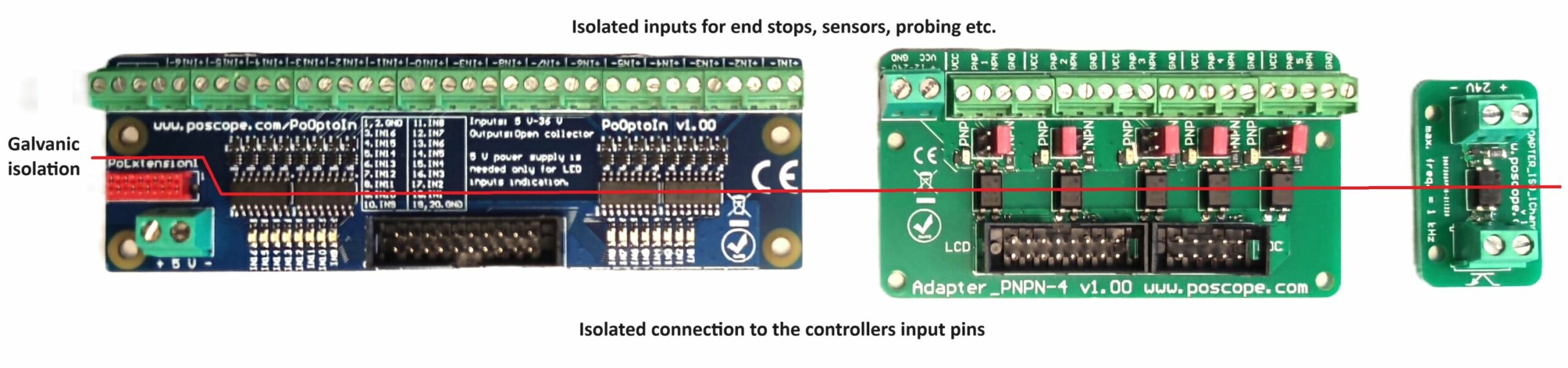
Such signals should be galvanically isolated before connecting them to the controller. That way, no direct electrical connection is established between the long cable and the controller itself. We offer several adapters for galvanic isolation of your signals from 16 channel industrial digital input isolator to 5 channel adapter PNPN for NPN and PNP sensors for easy connectrion to our CNC controller. We also have 1 channel isolation adapter board.
Also all other signal that are wired outside the electrical cabinet should be galvanically isolated from the CNC controller. That includes probing signal, floating head swith for plasma, spindle sensors etc. For isolating the USB communication, we offer USB isolator to remove the ground loops in the communication channels.
EMI management with CNC wiring
VFD noise and filtering
VFD is also very noisy part of electronics. It uses PWM modulation for 3 phase output for the spindle or any other kind of motor. There are a lot of radiated emissions on the input leads as well as on the output to the motor. It is recommended to buy and install filters for the signle phase or 3 phase input to the VFD that will significantly lower the noise.
For the output leads to the motor, a simple ferrite core can reduce the output interference in half. Just use big enough ferrite and wrap the output leads a few times around it.
Plasma cutter noise
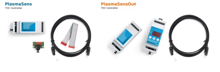
Plasma cutter is very powerful noise emitter. It is especially neccessary to galvanically isolate all the wires that are routed outside the electrical cabinet. Our PlasmaSens also feature optical cable that is galvanic isolation by itself. PlasmaSens unit should be mounted outside the main enclosure and only optical cable routed inside the electronics cabinet. Plasma cutter source should also be placed outside the cabinet.
Limit switches and floating head wires should all have galvanic isolation and output wires should be as close to the exit of the cabinet itself.

Related Posts