This blog article is mostly to explain the confusing PoKeys57CNC pinout, as some users reported it. There is a myriad of connectors and signals, some are labelled as ‘PoKeys pins’, others are not, some have special function (e.g. limit switch inputs), some are general purpose…
Short history of PoKeys devices
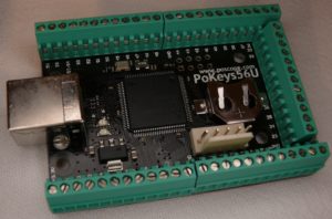
Let’s start with some history on how early PoKeys devices led to PoKeys57CNC device, which has a lot to do on how PoKeys57CNC is laid out. It all started in 2008, when PoLabs presented a humble PoKeys55 keyboard-emulation device (shown below). The keyboard emulation nature is the reason for the device name – ‘Po’ comes from PoLabs, while ‘Keys’ indicates a keyboard interface. It quickly grew relatively popular for controlling the Mach3 functions via keyboard shortcuts.
PoLabs kept the communication protocol open since the beginning and supported third party software development. The communication library was simple to use and gave everybody the access to all PoKeys features.
In 2008-2009, a Mach3 user wrote a simplistic Mach3 plugin based on PoKeys communication library and made the device as an IO device for Mach3. As an evolution, the device gained the support for potentiometers (using analog inputs), MPGs (using ‘Encoder’s feature) etc. At that point, PoLabs decided to take over plugin development and a new plugin for Mach3 was released in 2010.
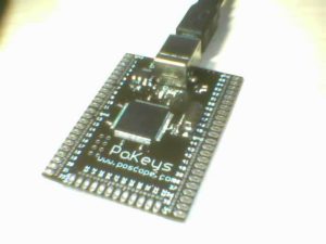
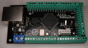
Later, in 2010, PoLabs presented a new PoKeys56 series family of PoKeys devices with more powerful hardware that allowed PoLabs to implement new features. PoKeys56E was released first, a PoKeys device (without keyboard emulation) with Ethernet interface. It allowed the devices to be positioned much further away from the PC. Later, PoKeys56U followed, which brought new PoKeys56 series features to USB devices also.
 |
 |
|---|
PoLabs started receiving questions on how to connect step/dir signals to the device to drive the stepper motors instead of using the disappearing LPT port in Mach3. This prompted the development of ‘Pulse engine’, a PoKeys device feature that allows the device to generate stepper motor signals. It allowed these signals to be generated based on the buffered motion data from Mach3. It could also use an internal motion planner to drive the stepper motors on itself in speed or position mode, which is needed to support homing and mach4 probing operations. The PoKeys56 series devices got this feature via a free firmware update. An MPG-jog mode was later added, which was superior to what Mach3 offered.
PoKeys devices are designed to be universal and resources must be shared among many features. Due to these limited resources, the internal Pulse engine motion controller could drive only 3 stepper motors at step rates up to 25 kHz. This was more than enough initially, but users wanted more…
Then, in 2013, PoLabs presented the new improved ‘Pulse engine v2’ with support for ‘external’ pulse generator and a PoKeysCNCaddon extension board. It was connected to a PoKeys device (either PoKeys56U or PoKeys56E) with 8 signals and allowed the PoKeys device to drive 8 axes at 125 kHz step rate, a much needed improvement over what basic PoKeys56 devices were capable of. PoKeysCNCaddon was equipped with dedicated inputs for limit/home switches and dedicated outputs with relays and open-collector outputs, which freed-up pins on the host PoKeys device.
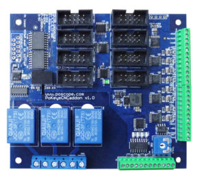
These dedicated pins were handled by the ‘Pulse engine’ directly and were not designed to be used as other pins on PoKeys device. Instead, these were designed to interface home and limit switches and be used in that regard.
Although the PoKeysCNCaddon had to be connected to PoKeys device with ‘only’ 10 wires, this process was prone to errors since each wire had to be separately connected to a specific pin of the PoKeys device. The increased interest in PoKeysCNCaddon extension card and users’ feedback on complexity of wiring it up led to a design of a new product.
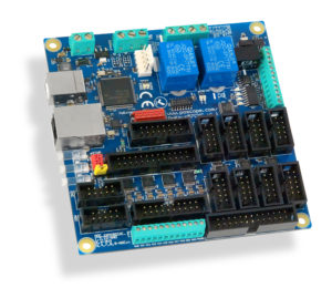
In 2013, development on a new device family, PoKeys57 series, started and PoKeys57U and PoKeys57E were released a year later. These two devices and a new firmware design allowed PoLabs to announce a new product in 2015 as a replacement for PoKeysCNCaddon. The fully fledged USB and Ethernet motion controller PoKeys57CNC is ‘born’.
PoKeys57CNC pinout explained
The PoKeys57CNC is a derivative of PoKeys57U, PoKeys57E and PoKeysCNCaddon devices. It features USB and Ethernet interfaces with full functionality of PoKeys57U and PoKeys57E devices – USB keyboard/joystick emulation, Modbus server etc. It shares the same API commands and is fully backwards compatible, so any software that supports PoKeys57U or PoKeys57E can ‘talk’ to the new PoKeys57CNC device.
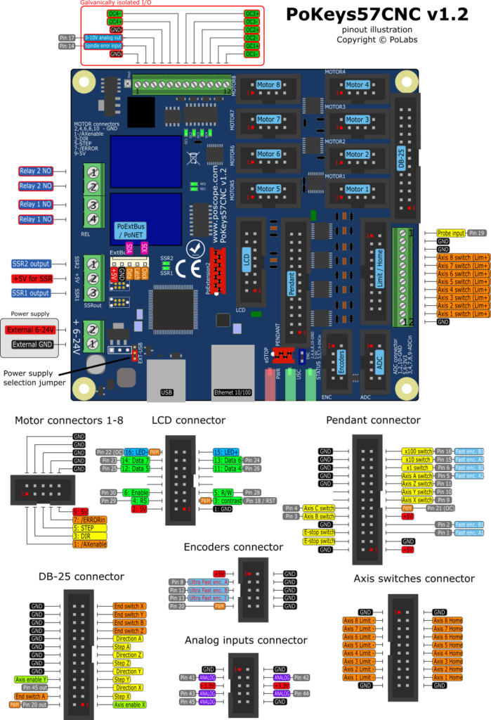
The functionality of PoKeys devices was grouped in PoKeys57CNC pinout and presented as separate connectors:
- Galvanically isolated I/O: this group contains 4 open-collector outputs (these are dedicated signals of the Pulse engine), 0-10V analog output (driven by the PWM via PoKeys Pin 17) and spindle error input (PoKeys Pin 14)
- Relays and SSR outputs: this group contains two relays and two open-collector outputs for external SSR (solid state relay), all dedicated signals of Pulse engine
- Motor 1 – Motor 8: eight 10-pin connectors with standard pinout for connecting stepper/servo motor driver. Each contains step, direction, enable outputs and an error input. All these signals are dedicated signals of the Pulse engine.
- Limit+ connector with probe input: this wire screw terminal contains inputs for limit (also home if shared with limit+ option is enabled) for all axes (these are dedicated inputs to Pulse engine) and an additional probe input (a PoKeys pin 19).
- Limit / Home connector: additional limit and home inputs for all axes (again, all are dedicated inputs to Pulse engine)
- DB-25 connector: a standard set of CNC-related signals that is compatible with most multi-axis driver boards that were designed for LPT ports. It contains step/direction signals and home/limit switch inputs for 4 axes (all these are dedicated signals of Pulse engine) with some additional signals (accessible via PoKeys pins 20 and 45).
- LCD connector: a standard set of signals for connecting an alphanumeric LCD to PoKeys device. PWM outputs via PoKeys pins 18 and 22 are used to set the LCD contrast and backlight brightness.
- Pendant connector: this connector contains most of the available general-purpose PoKeys pins. A PoPendant (or similar) can be connected to this connector or the signals can be used for other purposes.
- Encoder connector: contains PoKeys pins that are used for the ‘Ultra-fast encoder’ feature of PoKeys devices.
- ADC / Analog connector: contains remaining PoKeys pins that support analog to digital conversion (analog inputs).
What are PoKeys pins?
The signals labelled as ‘Pin xx’ (xx is a number between 1-55) are ‘PoKeys pins’. The general purpose PoKeys55, PoKeys56 and PoKeys57 devices have 55 physical connections (via wire screw terminals) with special features assigned to them based on hardware limitations. For example, pins 17 to 22 can be configured as PWM outputs, pins 41 to 47 as analog inputs, pins in the 22 to 30 range support LCD display signals, pins 8, 12 and 13 are used by the ultra-fast encoder etc. Software that uses these pins must be aware of their position and configure them accordingly. This is the main reason that PoLabs keeps special features assigned to the same pins in order to avoid the need for adapting software to each individual PoKeys device. This is greatly appreciated by the 3rd party developers that support PoKeys devices in their software.
As the result, ‘PoKeys pin’ on the connectors pinouts above don’t follow the connector pinout and Mach3/Mach4 software does not refer to the signals on each connector by their connector pin number, but by the PoKeys pin number.
Note: standard IDC-based connectors (the black ones used in the pinout diagram above) use zig-zag pin numbering scheme. See the encoders connector – first pin is marked in red as ‘1’. The pin right to it is pin 2 and the pin below 1 is pin 3. The numbers increase in the zig-zag pattern.
What are dedicated signals of Pulse engine?
The dedicated signals are something PoLabs introduced in PoKeysCNCaddon (see the history above) and are specific to Pulse engine. These signals are handled in completely different way to ‘PoKeys pins’. The dedicated signals have fixed function (limit+, limit-, home input, relay or open-collector output) and are scanned as required by the Pulse engine in PoKeys device. As such, these signals are not available to other PoKeys functions and can not be used as general purpose I/O signals. More informations about stepper motor driver: complete explanation-stepper motor driver.
Home/limit signals in Mach4
In Mach4, these dedicated signals are available as ‘Dedicated home/limit’ signals of ‘PoKeys <serial> PE’ device (PE stands for Pulse engine) in Mach4 Input and Output signal mapping dialog.
Since each axis can be configured to use either these dedicated switch inputs or general purpose PoKeys pins, the ‘PoKeys <serial> PE’ device in Mach4 also contains Limit and home status signals. These are statuses of home and limit inputs as perceived by the PoKeys device based on actual configuration. If PoKeys device is configured to use PoKeys pin 1 for home switch input on axis 1, the home status signal for axis 1 will indicate its status.
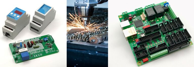
Please check also our CNC electronics:
- Stepper motor driver
- USB CNC CONTROLLER-PoKeys57CNC
- Homing sensor-PoHome1IRNPN
- Bipolar stepper motor driver – PoStep25-256
- PCB tester – PoStep25-256
- plasma voltage divider
- Introduction to CNC hardware – electronics
- plasma cutting equipment
- what is CNC plasma cutting
- what is CNC plasma floating head
- plasma cutter troubleshooting guide
- 4th axis for CNC
Related Posts