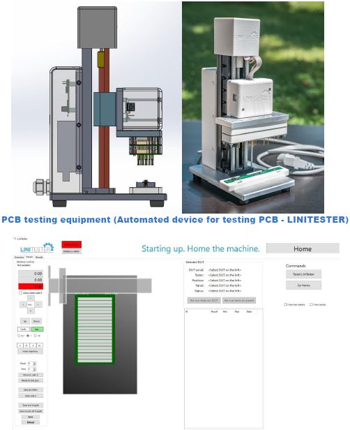
A blog article about a PCB testing equipment (Automated device for testing PCB – LINITESTER). From the idea to the useful custom made automated testing device. PoLabs team develop testing device for testing PCB in serial production. Device was build using a PoKeys57U device from CNC controllers device and stepper motor driver-complete explanation.
Table of Contents
Automated device for testing PCB – PCB testing equipment
In all electronics mass production, we have a testing devices. Polabs and our customers have needs for testing PCB, because the quality, productivity, and reliability are very important for us.
PoLabs developed two devices for testing PCB. Both devices have the same functionalities for testing, programming, the difference between devices is in productivity.
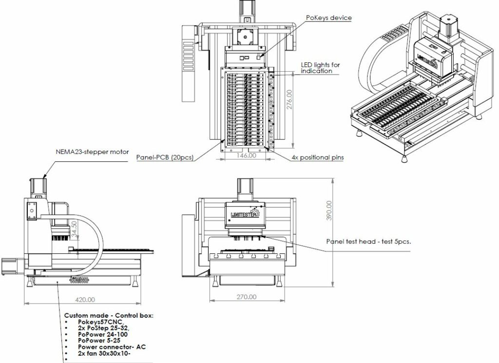
Panel tester has working area X-axis (220mm), Y-axis (260mm) and Z-axis have 40 mm working move, for most applications we have movements in Z and Y-axis, X-axis is stable. In the panel tester, we have a test indicator with LED lights to indicate good/not good parts and communicate with the PoKeys device (sending data). Test head in panel tester is in most cases for 5 PCBs at the same time.
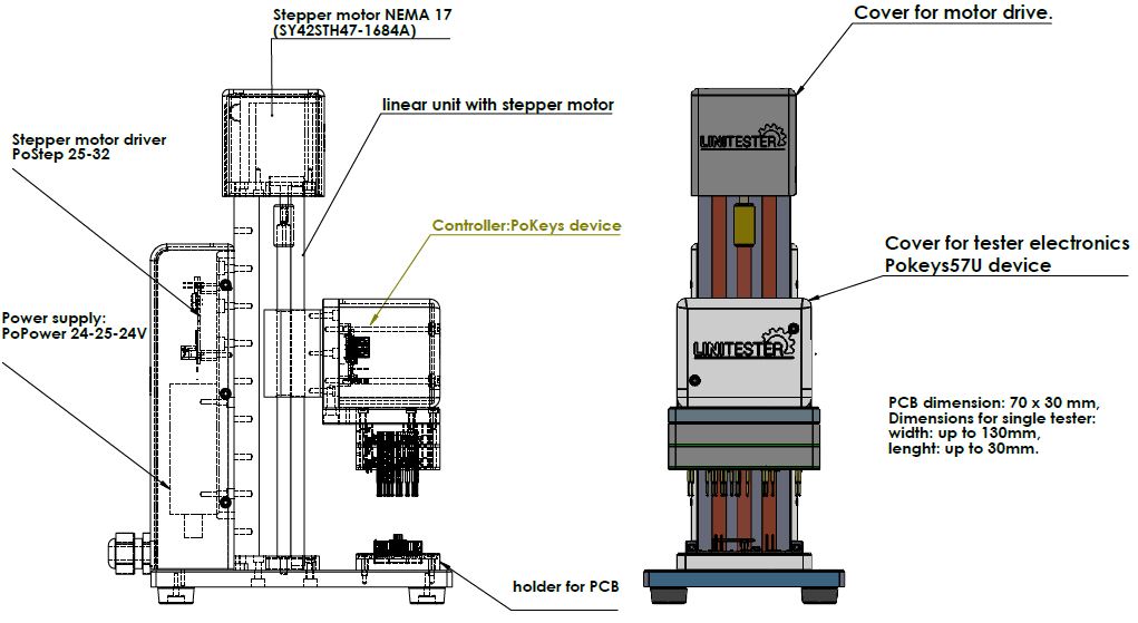
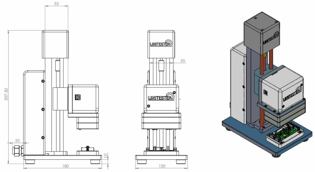
The tester for single PCBs has only one axis which moves the test head up and down to make contact with pogo pins to the PCB under test. Both devices have a good working area and are simple for work (exchanging PCB).
How to test a PCB board?
PoLabs for testing using the In-circuit testing method this method is currently the most robust and popular type of PCBA testing.
Testing method: electric probes (pogo pins) contact PCB and send currents through specific locations on the board at designed test points. These tests can check shorts and open circuits, solder defects, possibly missing parts, or incorrect orientation of parts. All functions of the tester include:
- Voltage and current measurement,
- serial communication check,
- microcontroller programming,
- serial number saving on server,
- checks of the different custom functionalities.
Electronic production includes many steps before we test parts: Firstly PCB design, Secondly: mechanical design, Thirdly hardware design, and software design.
Mechanical parts of LINITESTER – PCB testing device
Both devices for testing PCB we have mechanically 3D designed, manufactured, and assembled. Devices are still improving from project to project and requirements.
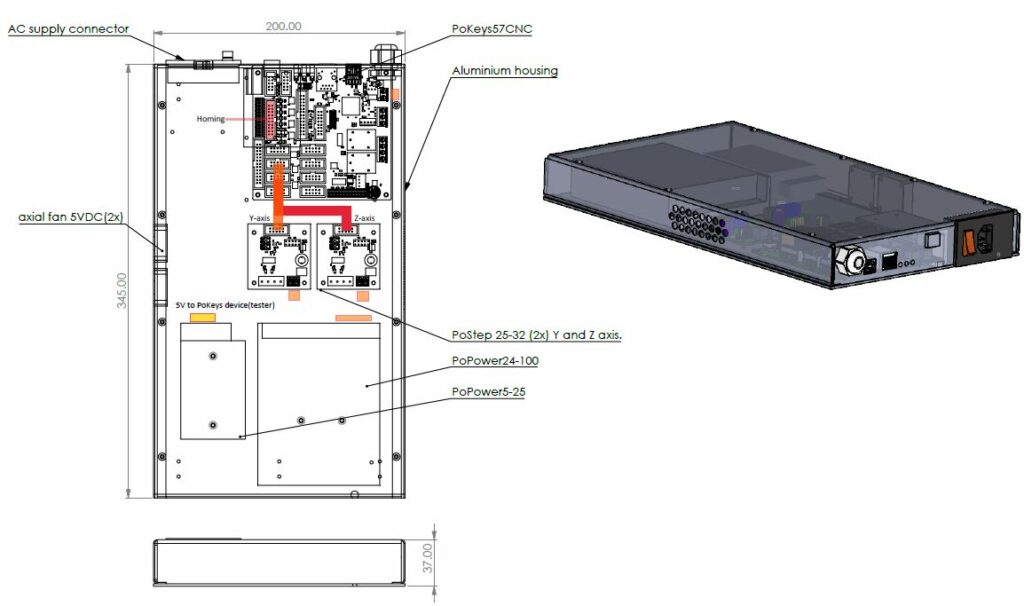
Single tester is single axis device that has motion linear axis developed by us and driven with a stepper motor, other aluminum holders for PCB-s and holder for tested PCB are custom made and most importantly assembled into the accurate device. Panel tester is in base designed and manufactured like CNC router-milling machine because the device must be rigid and accurate for serial testing.
PCB testing equipment – functional testing
First, we must say that the project had four areas that needed to be addressed. Firstly PCB-PCBA development, preparing for production, design test head and test indicator, secondly mechanical with motion unit and custom made mechanical design of the device, thirdly electric with drives and control logic and final software for tester device ( LINITESTER).
Electronic parts of Automated device for testing PCB
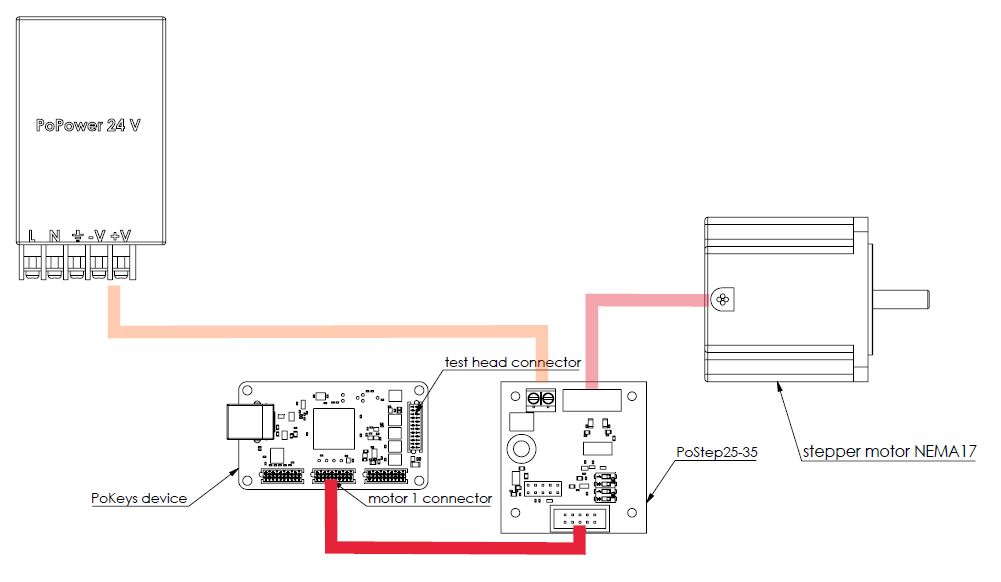
PoLabs is well known for its wide range of its own products and richly stocked online store. For our devices (machines), we of course used units from our store for most electronic components.
Parts:
- PoKeys57U,
- PoKeys57CNC,
- PoStep 25-32,
- end switch.
- Homing sensor-(blog)
- Linear axis
Power:
- Stepper motor NEMA17 / NEMA23,
- PoPower 5-25 5V 25W,
- PoPower 24-100 24V 100W,
- AC supply socket with switch.
First PCB test and adjustments
In the ICT method is very important the precision of mechanical components. During the assembly, we check the assembled parts and geometrical tolerances. The quality of mechanical components is base for an accurate and rigid device. After assembly, the device is checked mechanically and electrically so that it works properly in production.
The advantage of automated PCB testing equipment
The PCB in-circuit testing is one of the most robust and used types of PCBA testing. During testing, each component is tested individually by equipment. The tester checks for logic functionality. Unlike most other test methods, actually powers up the components.
- Fault coverage can be high as 98%,
- An efficient and quick method of testing mass-produced products,
- fast testing method,
- very low maintenance,
- very detailed test data,
- consistency of testing,
- can turn on and test LEDs,
- little space for operator errors / poor decisions making.
Conclusion about PCB testing equipment
The device is functional and works very well, and accurately.
If you have any questions please contact us, we will provide you with quality service.
More about
Please check also our latest blog posts. It can help you to improve your machines or get some ideas on how to even make them better.
- Bipolar stepper motor driver – PoStep25-256 – product
- PCB tester for PoStep25-256 – blog
- 4th axis for CNC – blog
- Introduction to CNC hardware – electronics – blog
- plasma cutting equipment – blog
- what is CNC plasma cutting – blog
- CNC plasma floating head – blog
- Plasma cutter troubleshooting guide – blog
PoLabs web page,
More information about Pokeys I/O devices.

