Here is a practical example of Arduino driving i2c relay board as a arduino relay module. PoRelay8 board with 8 relay outputs can be connected to any Arduino device if it can communicate via the I2C protocol. If 8 relay outputs do not satisfy your demands, additional up to 9 PoRelay8 boards can be daisy-chained over CAN bus, even with long cables between boards.
Table of Contents
How does relay module work with Arduino?
A smart relay is an electro-mechanical component that needs an electrical signal for excitation of the coil winding. An electromagnetic field will produce a mechanical force that will move the contacts. Since the Arduino can’t drive relay only with digital outputs we need an additional power stage to drive the relay’s coil. In most cases a FET transistor will do the job. That’s simple and will be just fine if we are talking about driving a few relays. The use of a larger number of relays can lead to opacity and lack of board output pins. Using a PoRelay8 as i2c relay board can fix all above mention problems. PoRelay8 relay module board use a standard I2C communication protocol that allows us to driving 8 relays with only two Arduino digital pins.
How many relays can an Arduino control?
Thanks to an integrated CAN bus on the PoRelay8 board Arduino can with a single I2C bus control up to 80 relays. Even more, Arduino can drive relay boards using a custom I2C address. However, using a multiple bridgeboard with its own I2C addresses allows theoretic driving more then 127 relay boards each chained with 9 relay boards using CAN bus. If we simplify we can control more than 10.000 relays using one Arduino board. If we are realistic, we are limited by the speed of data transfer and SW.
Connecting i2c relay board to Arduino Mega2560
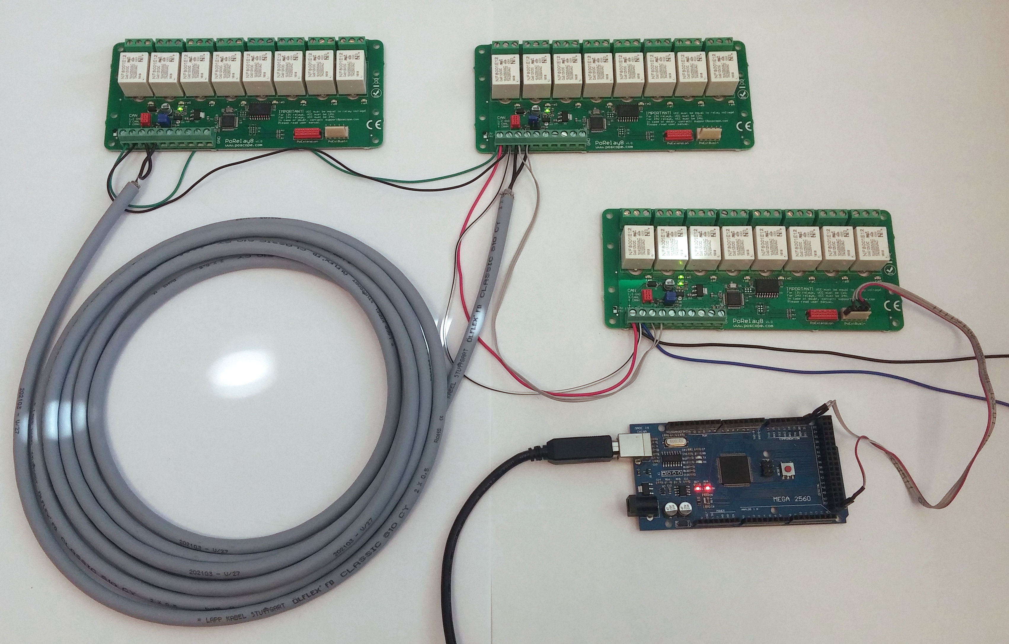
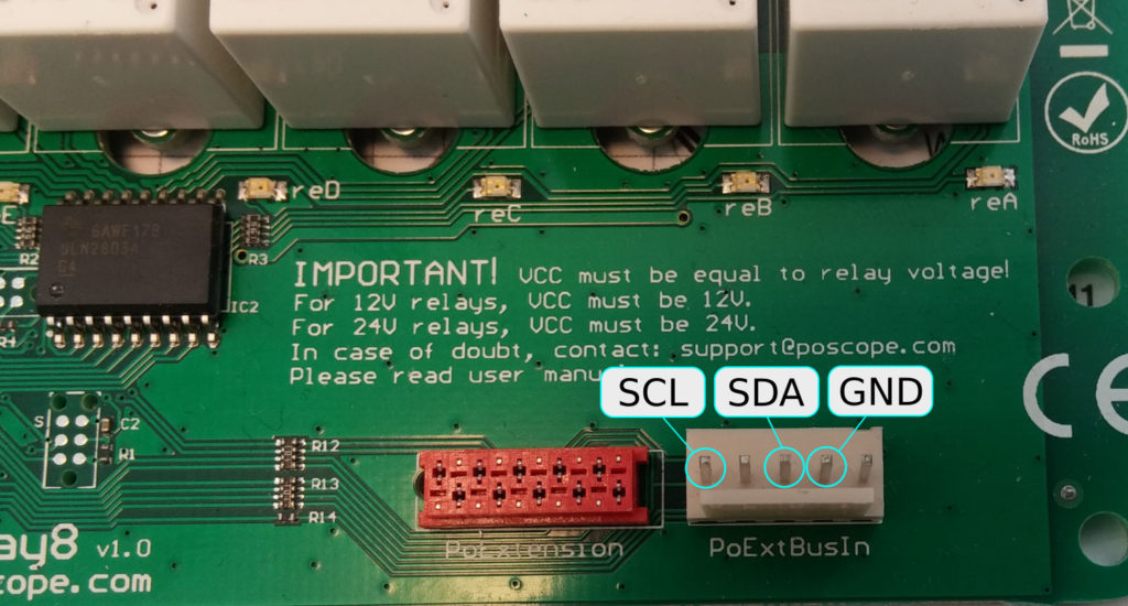
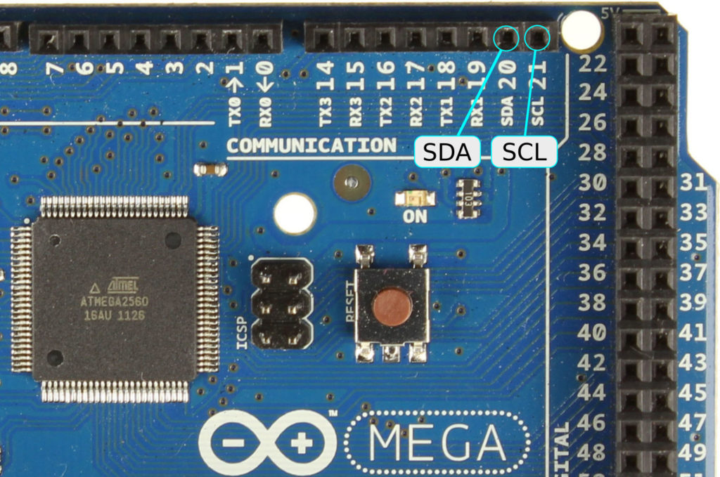
Connecting PoRelay8 to your Arduino Mega2560 is simple. Just connect together I2C pins and ground as is shown on pictures 1 and 2. On Arduino Mega pins 20 (SDA) and 21 (SCL) are used for I2C communication. For other devices, look at the following list:
| Board | I2C / TWI pins |
| Uno, Ethernet | A4 (SDA), A5 (SCL) |
| Mega2560 | 20 (SDA), 21 (SCL) |
| Leonardo | 2 (SDA), 3 (SCL) |
| Due | 20 (SDA), 21 (SCL), SDA1, SCL1 |
I2C bus requires a pull-up resistor on both lines. Mega2560 has pull-ups already integrated and do not require external resistors. Other I2C capable Arduino devices do not have integrated pull-ups and external resistors should be added. The Pull-up resistor value depends on bus capacitance and communication speed. 4,7 kΩ resistors connected between SDA, SCL and power supply should be appropriate for most cases. For other allowed resistors values, please consider I2C bus specifications.
Before powering up your boards, do not forget that PoRelay8 board require separate 12V or 24V power supply (depends on relay type on your board, required power supply is marked on PCB next to screw terminals).

Connecting more arduino relay modules – PoRelay8 with CAN bus
Up to 10 boards can be connected to your Arduino board with use of a CAN bus, extending a number of relay outputs to 80. Another great feature of CAN bus is the possibility to use long cables if needed.
When connecting multiple relay boards to your device, first board is connected directly to device on I2C bus and functions as a bridge between I2C and CAN bus. All other boards are connected to the bridge board over the CAN bus in daisy-chain fashion.
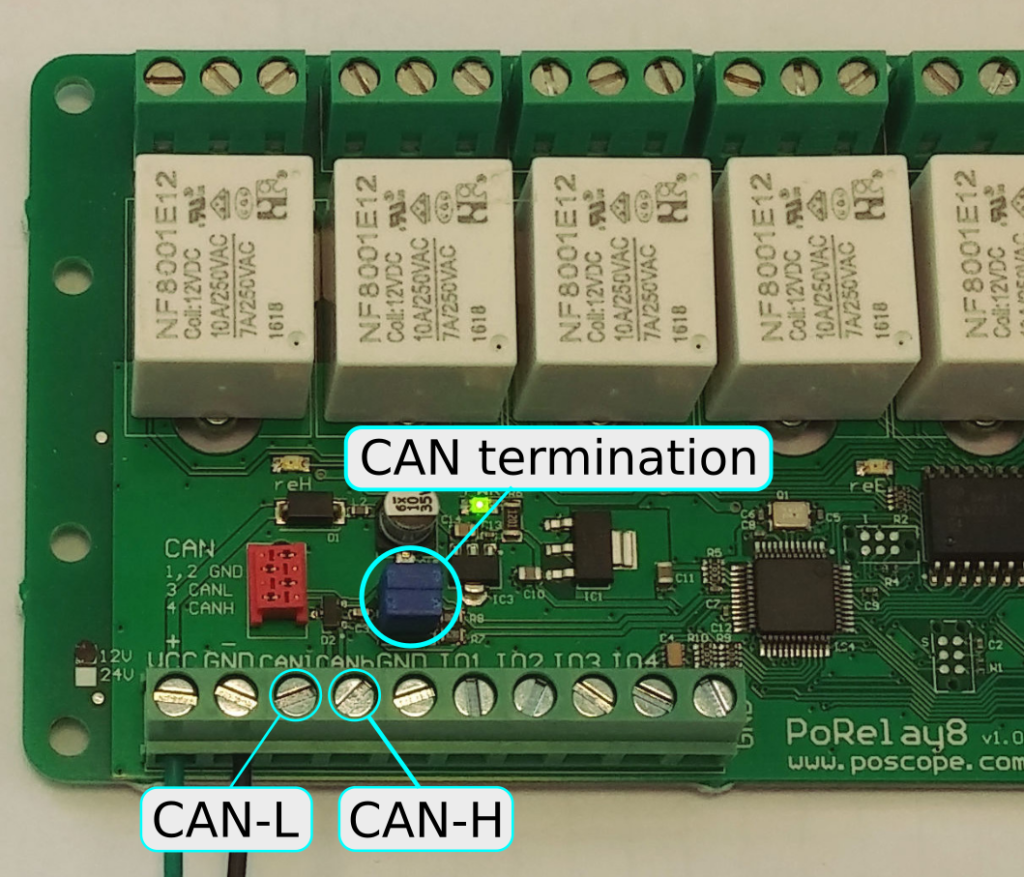
CAN bus connection can be made with flat cable with Micro-MaTch connectors (red connector on the relay board) or with use of screw terminal connectors as our case. All connections (picture 1) marked CAN-L and CAN-H must be connected together in parallel (connect all CAN-L terminals together with one wire, use a separate wire for all CAN-H terminals). If you are going to use long cables, use of shielded twisted pair cables is recommended to decrease possible interferences.
Both ends of CAN bus must be terminated with resistors, which are already integrated on all PoRelay boards. They can be enabled or disabled with resistors, as is shown on picture 4. For correct jumper orientation please check the PoRelay manual or see picture 4.
Arduino CAN & i2c relay board wiring on more than one PoRelay8
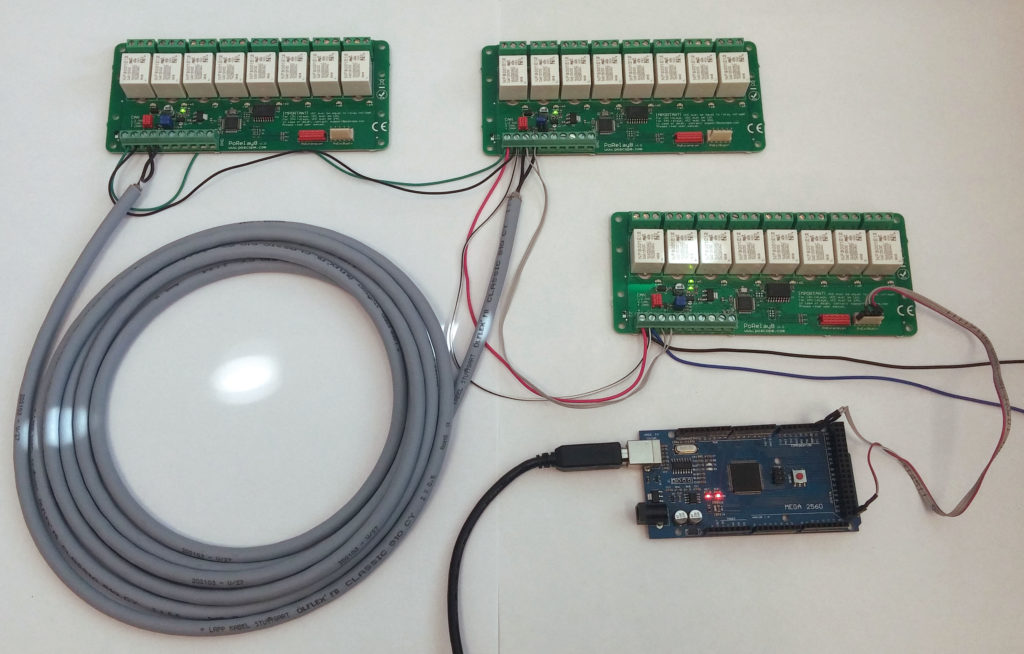
In this chapter communication with 3 PoRelay8 boards is presented with a chaser code example for Arduino Mega2560. The same code should work well with any Arduino device with support for I2C protocol. If you not using Mega2560, do not forget to add pull-up resistors to both I2C lines.
From the Arduino side, all communication with PoRelay8 boards is executed over I2C bus with PoRelay8 acting as a bridge. The communication of the bridge relay boards with other boards takes place via the CAN bus.
Any PoRelay8 board can act as a bridge board.
Communication with bridge board
Communication with the bridge board is simple with use of the Arduino wire library, which is included at beginning of our program. If you want to find out more about this library, you can check the official documentation. The I2C address of the PoRelay8 bridge board is 0x7B. All PoRelays boards have this I2C address preprogrammed. To set the outputs of bridge, 3 bytes must be send over I2C. First is set outputs command, followed by byte with outputs values and checksum. The checksum is sum of all sent bytes, masked with 0xFF, as sum must not exceed 255. To turn on relay A on bridge board following bytes must be sent over I2C:
| Set ouputs | Output values | Checksum |
| 0x10 | 0x01 | 0x11 |
Setting of bridge PoRelay8 outputs is implemented in the bridge_set_outputs function of our code example.
Communication with other boards in a daisy-chain
Sending data to other boards (connected to the bridge over the CAN bus) is little more complicated. To send data over CAN bus we must start with sending 0x40 value over I2C. This is interpreted as send-over CAN command. Follows CAN message ID, which consists of two bytes: 0x01 and 0x08. Next byte is number of data bytes we want to send, followed by all data bytes. Last byte is checksum of all sent bytes.
Reading data that was received from CAN bus is simple. It starts with writing 0x41 byte to I2C bus and reading from I2C expected number of received bytes from CAN bus. First read byte should have value 0x1A, as marker that data was received and is valid.
In our example, we have 2 PoRelay8 boards connected to bridge over CAN. Now we have to find out addresses of two boards connected to bridge. This can be done by issuing CAN identify command. To do this, we write to I2C bus next bytes:
| Send over CAN | Data length | CAN message ID | Data | Checksum | |
| 0x40 | 0x01 | 0x08 | 0x01 | 0x10 | 0x5A |
In this case, the data part with the value of 0x10 is interpreted as a request for identification. Each board connected to the bridge will respond with 12 bytes long CAN message containing information about it. Received bytes from 8 to 12 represent boards unique address, that must be used when setting outputs on desired board.
To set the outputs of desired board connected over CAN bus, the following sequence must be written to I2C:
| Send over CAN | Data length | CAN message ID | Data | Checksum | ||||||
| Set outputs | Board address | Outputs | ||||||||
| 0x40 | 0x05 | 0x08 | 0x06 | 0x20 | 0xXX | 0xXX | 0xXX | 0xXX | 0x01 | 0xXX |
This sequence of bytes will turn on relay A on board with the selected address.
Our example is a chaser, which will turn on all relays on all boards in series, beginning with relay A on the bridge board. It is important to know, that in this case, we are always scanning for connected boards at the start of the program. The order of arduino relay module PoRelays boards connected on the CAN bus will vary, as boards are numbered in order as they answer. When identifying boards, it is impossible to know which board will reply first. For full control over your boards, their CAN addresses should be hardcoded in your program.
Arduino relay module PoRelay8 – code example
// Example code for Arduino driving relay on PoRelay8 board //

#include

#define CAN_SEND    0x40
#define CAN_READ    0x41
#define IDENTIFY    0x10
#define SET_OUTPUTS 0x20
#define CAN_ID_H    0x01
#define CAN_ID_L    0x08

#define BRIDGE_ADDRESS 0x7B

byte porelays[10][4];
byte found_boards;

void setup() {
  Wire.begin(); // Initialize wire library for I2C communication
  Serial.begin(9600); // Configure serial port

  found_boards = CAN_identify(); // Identify devices connected to CAN bus
}

void loop() {
  byte chaser = 0x01;
  int i = 0;

  while( chaser )
  {
    bridge_set_outputs(chaser);
    delay(300);
    chaser = chaser  << 1;
  }
  bridge_set_outputs(0x00);

  while (i<found_boards)
  {
    chaser = 0x01;
    while( chaser )
    {
      CAN_set_outputs(chaser, porelays[i]);
      delay(300);
      chaser = chaser  << 1;
    }
    CAN_set_outputs(0x00, porelays[i]);
    i++;
  }
}

void bridge_set_outputs(byte outputs)
{
  byte checksum = (SET_OUTPUTS + outputs) & 0xFF;

  byte data[] = { SET_OUTPUTS, outputs, checksum };
  Wire.beginTransmission(BRIDGE_ADDRESS); // transmit
  Wire.write(data, 3);
  Wire.endTransmission();    // stop transmitting
}

void CAN_set_outputs(byte outputs, byte address[])
{
  byte checksum = CAN_SEND + 0x06 + CAN_ID_H + CAN_ID_L + SET_OUTPUTS + address[0] + address[1] + address[2] + address[3] + outputs;
  byte CAN_set_outputs[] = {CAN_SEND, 0x06, CAN_ID_L, CAN_ID_H, SET_OUTPUTS, address[0], address[1], address[2], address[3], outputs, checksum };

  Wire.beginTransmission(BRIDGE_ADDRESS); // transmit
  Wire.write( CAN_set_outputs, 11 );
  Wire.endTransmission();    // stop transmitting
}

int CAN_identify()
{
  byte response[13];
  byte checksum = CAN_SEND + 0x01 + CAN_ID_H + CAN_ID_L + IDENTIFY;
  int i,k;
  byte CAN_dentify[] = {CAN_SEND, 0x01, CAN_ID_L, CAN_ID_H, IDENTIFY, checksum};

  Wire.beginTransmission(BRIDGE_ADDRESS); // transmit
  Wire.write( CAN_dentify, 6 );
  Wire.endTransmission();    // stop transmitting

  delay(200); // Wait 200ms for all responses

  k = 0;
  do
  {
    Wire.beginTransmission(BRIDGE_ADDRESS); // transmit
    Wire.write( CAN_READ );
    Wire.endTransmission();    // stop transmitting

    Wire.requestFrom(BRIDGE_ADDRESS, 13);    // request 13 bytes from slave device

    // Read received bytes

    i = 0;
    while(Wire.available())
    {
      response[i] = Wire.read();

      if ( response[i] != 0x1A && i == 0 )
      {
        break;
      }

      if ( i >= 8 && i <= 11 )
      {
        porelays[k][i-8] = response[i];
      }

      i++;
    }
    k++;
  } while ( response[0] == 0x1A );

  // Print found boards addresses to serial port, output is in HEX format
  for (i = 0; i < k-1 ; i++)
  {
    Serial.print("CAN board ");
    Serial.print(i);
    Serial.print(" address: ");

    for (int j = 0; j < 4 ; j++)
    {
      Serial.print(porelays[i][j], HEX);
      Serial.print(" ");
    }
    Serial.print("\n"); // New line
  }

  return k-1;
}
If you need higher – 48V version of programmable relay it is also available.
Please check also our other electronics-related blog articles.
Also if you need information about PoLabs – Pokeys product, Here are some useful links:
Please check also our latest blog posts. It can help you to improve your machines or get some ideas on how to even make them better
- Stepper motor driver-complete explanation
- USB CNC Controller – PoKeys57CNC,
- Homing sensor.
- Bipolar stepper motor driver – PoStep25-256 – product
- PCB tester – for PoStep25-256 – blog
- 4th axis for CNC – blog
- Introduction to CNC hardware-electronics – blog
- plasma cutting equipment – blog
- what is CNC plasma cutting – blog
- What is CNC plasma floating head – blog
- plasma cutter troubleshooting guide – blog
- Torch height control – THC
Related Posts