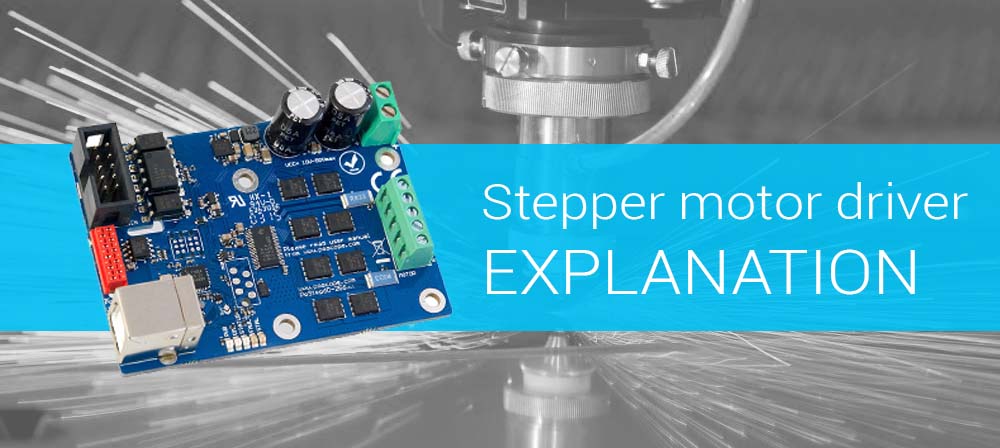
This stepper motor driver user manual contains information required to configure over a USB and run the PoStep60 driver.
Please read the manual carefully to avoid damage to the driver. This section covers the stepper motor driver explanation – general description, instrument specifications and characteristics.
Table of Contents
General symbols for these instructions
A few symbols are used throughout this manual that you should be aware of in order to complete certain tasks safely and completely.
These symbols have different degrees of importance as described below:
NOTE! Tells you other important information.
CAUTION! Tells you something that could be considered to reduce a risk of failure or malfunction.
WARNING! Tells you something that could cause damage to a property.
Stepper motor driver user manual – Description
The PoStep60 driver incorporate advanced stepper motor controller and external N-channel MOSFETs to drive a bipolar stepper motor or two brushed DC motors. A micro-stepping indexer is integrated, which is capable of step modes from full step to 1/256-step. An ultra-smooth motion profile can be achieved using adaptive blanking time and various current decay modes, including an auto-mixed decay mode. A simple step/direction or PWM interface allows easy interfacing to controller circuits. An I2C serial interface can further be used to control all the driver functions including position control on board. All running parameters (output current (torque), micro stepping, step mode, decay mode…) can be set over USB and stored on board for standalone operation. Internal shutdown functions are provided for over current protection, short circuit protection, under voltage lockout and over temperature. Fault conditions are indicated via a FAULT LED, and each fault condition can be read in configuration software.
PoStep60 features
- up to 6,0 Amps Phase Current
- advanced settings available through USB connection
- compatible with 4, 6, and 8 wire stepper motors of any voltage
- +10 VDC to +50 VDC Power Supply
- up to 256 Micro-steps per Step
- various modes of decay mode for smoother moving of motors
- 3,3V and 5V logic compatible inputs
- 250 kHz Max Step Rate
- 0 °C To 85 °C Operating Temperature
- LED Power and Status Indicator
- Small Size: 54 mm X 75 mm
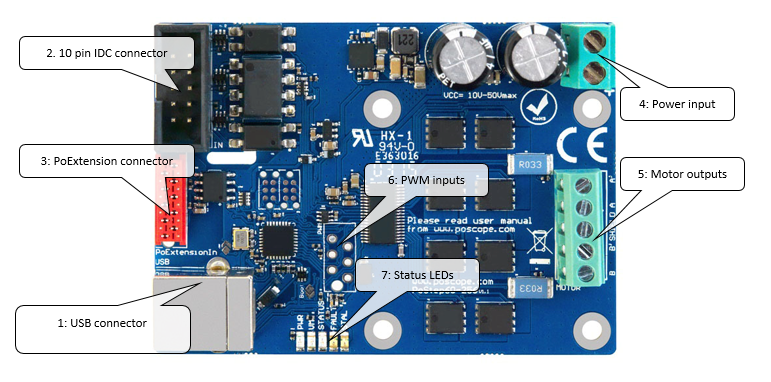
Connection diagram
Board use requirements
To properly operate the PoStep60 driver using external controller following connections need to be setup: step, direction and enable inputs; 10-50 VDC power supply, connected bipolar stepper motor before applying power.
CAUTION! Please make sure bipolar stepper motor is connected before applying power.
Connection and setting
- Mount PoStep60 driver firmly to a stable surface. If PoStep60 is mounted to a conductive (metal) surface, please make sure the driver is properly isolated.
- Connect USB cable (1) to your PC and run PoStep user application
- Please setup running parameters (output current (torque), micro stepping, step mode, decay mode…) using PoStep user application.
- Connect step, direction, enable and GND from PoStep60 (2) to controller or BOB
- Connect steeper motor (5) using one of wiring options bellow(
- Connect power supply (4)
- Complete explanation – Stepper motor driver.
WARNING! Please make sure power input polarity is correct. Double check before powering up the driver. Reverse power input polarity results in permanent device failure.
PoStep pinout
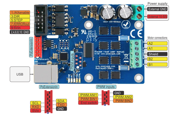
Stepper motor connection
10 pin IDC connector pinout
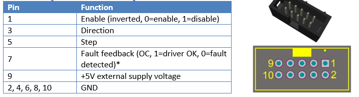
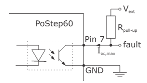
*Fault feedback signal is an open-colector signal. External pull-up resistor is needed to function properly (please see Figure 2). For input and open-collector output limiting values please refer to Section 6 – Technical specifications.
NOTE! Please note some of the drivers are showing failed Under Voltage Lockout (UVLO) fault status when disabled and supply voltage within required limits. The fault is removed after driver is enabled and supply voltage within limits.
Stepper motor connections
CAUTION! To avoid malfunctions please make sure the phase winds are connected correctly. Resistance between leads of different phases is usually > 100kΩ. Resistance between leads of the same phase is usually < 100Ω.
NOTE! Simple method of finding correct pairs of each winding wires is as follows (before proceeding none of the motor wires should be connected): take two random wires and short circuit them. Try rotating the stepper axis. If the pair is matching the resistance while trying to rotate the motor is much higher comparing to when none of the wires is short circuited.
NOTE! On the motor connector on the PoStep board there is a shield pin available (in the middle). Please use proper shielding techniques for best performance.
The drive will work with 4-wire, 6-wire or 8-wire stepper motors.
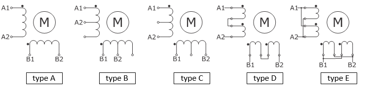
4-wire motors (type A)
are truly bipolar, and can only be run as such.
6-wire motors
can be wired two ways to work with the bipolar drive.
The first is half-winding (type B): In this method, one end wire, and the center-tap wire of the phase is used. The other end is insulated and left unused. This method uses unipolar nameplate current specifications, and will produce nameplate torque.
The second is series winding (type C): In this configuration, the center-tap is insulated, and unused. This method uses all of the wiring per phase, but has double the number of wire turns as halfwinding or unipolar mode. Because of this, the amperage requirement becomes half the nameplate rating. Because the wire in the coil can handle more current than ‘half’, motor manufacturers will often “boost” the torque rating by specifying currents up to 71% of unipolar rated current while running in series mode. This is fine for FULL step motor drives, but not necessarily so good for microstepping drives. Using this much can smear microstepping smoothness and accuracy. Any extra torque achieved by this method will generally be lost to machine vibrations due to loss of microstepping smoothness. The best performance will be somewhere between the 50% and 71% current rating.
The advantage of using series winding is that lower power drives may be used. For example a unipolar motor rated for 4.0A/phase running in series requires only 2.0A/phase to achieve the same torque. The disadvantage of this method is that it raises motor inductance, which in turn, slows motor coil charging time. Since proper torque is reached only when the coil has charged to the required level, the longer it takes to charge, the longer until full torque is achieved. This leads to slower full torque stepping rates. Conversely, a half-winding configuration requires full nameplate rated current, but if the drive is capable of this, the advantage is that rated torque can be achieved twice as fast as series winding (using the same voltage, when comparing half-winding and series).
8-wire motors
can be run in paralell (type E) or serial (type D) mode. Parallel mode needs higher current, has lower inductance and better torque, Serial mode needs lower current and has lower torque. Please read also 6-wire motors.
DC motor connection
6 pin PWM connector pinout
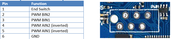
All PWM connector input pins has on board pull-up resistors. The pins can be either open-collector toward GND or push-pull driven. For input limiting values please refer to Section 6 – Technical specifications.
NOTE! PWM AIN1 and PWM AIN2 inputs are inverted.
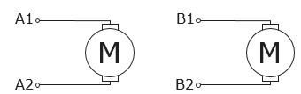
DC motor connection
The PoStep driver can be configured to enable direct control the state of the output drivers. This allows for driving up to two brushed DC motors. First DC motor is connected to terminals A1 and A2 and second DC motor to terminals B1 and B2. Speed and direction of DC motor rotation is controlled by PWM AINx and PWM BINx for first and second motor respectively. Driver allows connection of only one DC motor on A or B terminals as well as two DC motors.
CAUTION! Please make sure driver is configured to support DC motor drive. If not the DC motor can randomly rotate in speed and direction due to active micro stepping indexer.
NOTE! Full-scale current value still applys when in DC drive mode. Idle current is not applicable and is not being used.
PoStep LEDs
There are five LEDs on the PoStep board showing status.
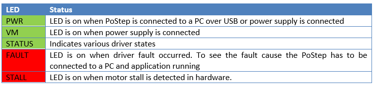
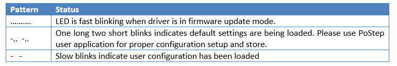
Status LED
Status LED is used to indicate various PoStep driver states.
Requirements
- One available USB 1.1, USB 2.0, or USB 3.0 port
- USB HID device driver enabled operating system (Windows 98 SE/ME/2000/XP/Vista/7,8,10)
- Included software requires Windows 2000/XP/Vista/7,8,…
- Microsoft Visual C++ 2010 Redistributable Package (x86 or x64) or Microsoft Visual Studio 2010 needs to be installed on the system prior running PoStep60 application.
Installation
PoStep60 is USB HID compliant device and as such require no additional drivers for operation.
To operate the device user software installation is necessary on a target system.
NOTE! – The program can’t start because MSVCR100.dll is missing from your computer. If application fails to start showing above message most likely “Microsoft Visual C++ 2010 Redistributable Package” has to be downloaded from MS pages and installed prior running PoStep60 application
NOTE! – The application was unable to start correctly (0xc000007b). Click OK to close the application. If application fails to start showing 0xc000007b error please install “Microsoft Visual C++ 2010 Redistributable Package (x86)” no matter you have 64-bit MS Windows operating system running.
Stepper motor driver user manual – Technical specifications
Electrical specification – limiting values

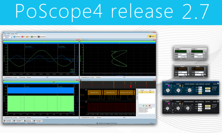
User application
User application enables various interactions with PoStep60 driver. The application enables setting of all the vital driver parameters including driver current (active, idle, and overheated values), micro-stepping value, driver name for later recognition, and advanced control setting values. Moreover, the application includes basic driving capabilities for stepper motors as well as two DC motors. For the stepper motor there is simple step/direction mode and more advanced onboard speed profile feature for out-of-the box drive of stepper motor. For DC motors drive there are two PWM channels with adjustable PWM values and directions. The application also monitors input statuses and driver status itself (temperature, mode, fault,…)
PoStep60 main application GUI
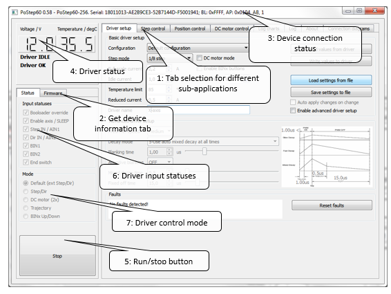
Figure notes:
- Tab selection for different sub-applications – please use tabs to navigate between sub-applications
- Click to get device information such as serial number, mode status, …
- The application title bar displays connection status of PoStep device. If a device is connected a serial number is displayed and if not “not connected” message is displayed. Please note only one device at same time can be connected.
- Driver status – The section displays real-time data of a driver connected if the driver is in application mode.
- Stop/Run button disables and enables PoStep driver. Useful feature when in various control modes.
NOTE! Please note enable signal is shared between external “Enable” input. Disconnected external signal when using application driver control features.
6. Driver input statuses displays current driver input statuses
7. Driver control mode displays current driver control mode
NOTE! Driver real-time values are only available when driver is in application mode. In bootloader mode all driver features are disabled.
PoStep driver status
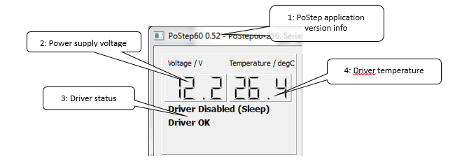
Figure notes:
- PoStep application version info – please check for latest update of PoStep application.
- Power supply voltage – displays main power supply voltage.
- Driver status – displays driver statuses
- Driver temperature – displays main power supply voltage.
CAUTION! The displayed temperature value may differ from the actual driver temperature due to indirect contact. Parts of the diver can have higher temperature than one displayed and as such might cause you burns if touched.
Driver statuses
- Driver active – there was a signal change in step/direction inputs in the last 10 seconds. Full-scale active current value is set
- Idle – there was no change on step/direction inputs for more than 10 seconds. Idle current value is set
- Overheated – when driver exceeds limit temperature values drivers goes into overheated mode. Reduced current value is set
- Fault detected – displays that at least one of possible driver faults were detected. Please check fault type in Advanced settings.
Input statuses
The application shows real-time data of all the driver IO pins – Figure 7 (tick represents high level):
- Bootloader override – the pin should always be high
- Enable axis / SLEEP – high level enables diver operation. Low level puts the driver to sleep mode
- Step IN / AIN1 – this is Step input signal in stepper motor operation or Motor 1 PWM control AIN1 when in DC motor control mode
- Dir IN / AIN2 – this is Direction input signal in stepper motor operation or Motor 1 PWM control AIN2 when in DC motor control mode
- End switch – end switch input statusBIN1 – Motor 2 PWM control BIN1 when in DC motor control mode
- BIN2 – Motor 2 PWM control BIN2 when in DC motor control mode
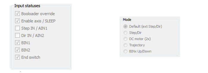
Driver control modes
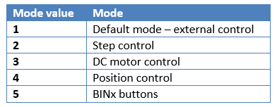
Driver control mode section displays current mode of the driver – Figure 8.
- Default (ext Step/Dir) – this is the driver default state which enables Step/direction control using external controller. Enable axis, Step IN, and Dir IN inputs shall all be connected for proper operation.
- Step/Dir – in this mode driver generates the driving signals. The mode is mainly used for driver settings adjustments – fine tuning. Please see subsection 4 Step control.
- DC motor – two DC motors can be controlled using direct PWM signals. Please see subsection 6 DC motor control.
- Trajectory – in this mode the driver take over controller parts of motion planning. Required position and speed profile parameters can be set. Please see subsection 5 Position control.
Basic user control of the PoStep driver
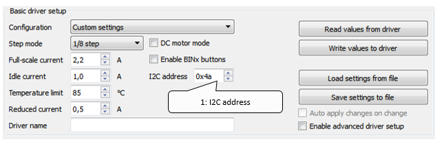
Basic user control section enables user selection of predefined driver configuration sets, setting currents: full scale, idle, overheated reduction, and temperature limit. Moreover, the basic manipulation with driver data is enabled: readout, change, and store. Furthermore, each of the drivers can be set an unique name for easier identification.
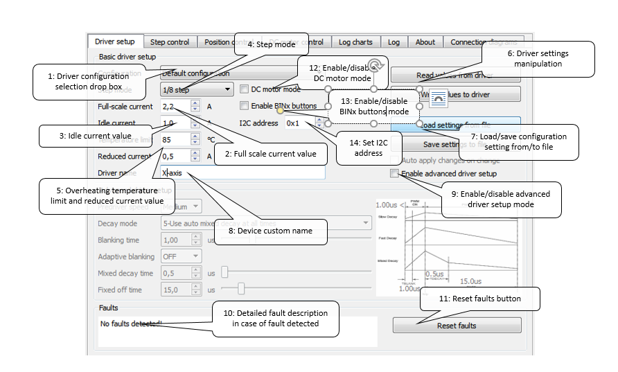
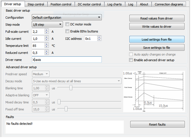
- Driver configuration selection drop box – select one of predefined configurations. Use default configuration if you are not familiar with motor performance parameters.
- Full scale current value – setup required motor current value.
NOTE! Please follow stepper motor datasheet when setting driver values. Setting higher current value than nominal motor current may result in changed characteristics of PoStep motor driver (overheating, motor ringing,…) due to motor running out of specs.
- Idle current value – setup idle current – idle current is a driver current when there is no activity on “Step/Dir” inputs for more than 10s.
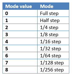
- Step mode – select a step mode between full step and 1/256-step (256 micro steps) mode.
- Overheating temperature limit and reduced current value – setup a temperature limit at which driver reduces driver current to protect driver from possible overheating.
- Driver settings manipulation – enables reading/writing configuration to/from PoStep60 driver
- Read values from driver – reads driver configuration settings currently set on the driver.
- Write values to driver – writes driver configuration settings and store them to a non-volatile memory on the driver. The settings are read and loaded each time driver is powered or reset.
NOTE! Any change in configuration settings made in application is not valid to driver until confirmed by “Write values to driver”.
- Setting files – enables loading/saving driver configuration settings from/to file
- Load settings from file – load driver configuration settings previously saved.
- Save settings to file – save currently set configuration to specified file.
- Device custom name – displays or change driver custom name
- Read custom name – reads driver name
- Write custom name – writes and stores driver name
- Enable/disable advanced driver setup mode – by checking advanced setup mode is enabled allowing setting advanced parameters
- Detailed fault description in case of fault detected – further describes detected fault and possible cause of the fault
- Reset faults – press the button to reset driver faults
- DC motor mode – Enable or disable DC motor mode
- DC motor mode – Enable or disable BINx buttons mode
- I2C address – Sets an address of the PoStep60 driver when using I2C communication
Advanced settings
WARNING! The advanced settings shall only be used by a person with a strong knowledge in motor control. There is a chance of setting combination that may results in permanent device failure.
In stepping motors, current regulation is used to vary the current in the two windings in a sinusoidal fashion to provide smooth motion. An ultra-smooth motion profile can be achieved using advanced settings such as blanking and decay time, and various current decay modes, including an auto-mixed decay mode.
The current through the motor windings is regulated by an adjustable fixed-off-time PWM current regulation circuit. When an H-bridge is enabled, current rises through the winding at a rate dependent on the DC voltage and inductance of the winding and the magnitude of the back EMF present. Once the current hits the current chopping threshold, the bridge disables the current for a fixed period of time, which is programmable between 500 nS and 128 us. After the off time expires, the bridge is re-enabled, starting another PWM cycle.
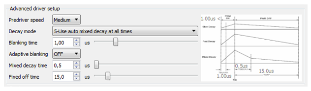
NOTE! When setting up the driver various compromises need to be considered such as:
-
Higher the input voltage longer the fixed off time has to be to control the required current,
-
Higher the input voltage lower the step mode,…
Step control
The application enables simple internal control of step/dir pins. It allows a test of basic driving capabilities of the PoStep60 driver.
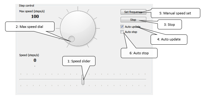
- Speed slider – use this slider to set step speed. Please note the maximum value is limited by “Max speed” value.
- Max speed dial – set maximum step speed to limit the step speed value set by “Speed” value.
- Stop – stops internal step/dir generator and switch the pins control to external controller.
- Auto update – if checked, any change in step speed value is sent to driver immediately.
- Manual speed set – send new step speed value to driver if “Auto update” is disabled.
- Auto stop – when checked step speed resets to zero when slider is released.
NOTE! If driver is used in combination with external controller or BOB please make sure to stop the application step/dir control by pressing button “Stop”. This way external controller takes over control of the step/dir pins again.
Position control
Simple position control algorithm is implemented in the driver. The driver moves to required position using standard “Trapezoidal motion profile” where acceleration, deceleration, and maximal speed is defining the profile. Required position can be set using input box or slider. End switches (NC or NO; please note – end switch reacts only on change of end switch state.) and position limits can be used to define/limit a range of movement. The provided position control allows a test of basic driving capabilities of the PoStep60 driver and is not intended to replace external controller.
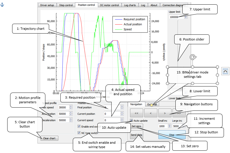
- Trajectory chart – displays required and actual position and speed charts
- Motion profile parameters – Trapezoidal motion profile parameters: acceleration, deceleration, and maximum speed
- Required position – set and displays (slider) required position
- Actual speed and position – displays actual speed and position values
NOTE! End switch reacts only on change of end switch state. Position change request after end switch touched can be set in either direction.
- Position slider – required position can be set using slider
- Upper limit – limits final position.
NOTE! If current position is out of new position limit values set then required position will adjust accordingly and motor shall move if Auto update is enabled.
- Lower limit – limits starting position
- Navigation buttons – set required position by a step defined by increment settings (11)
- Auto update – send new values to driver automatically if checked
- Increment settings – defines Small and Large increments for navigation steps
- Stop button – stops position movement immediately (no deceleration profile applied)
NOTE! If driver is used in combination with external controller or BOB please make sure to stop the application Position control control by pressing button “Stop”. This way external controller takes over control of the step/dir pins again.
- Set zero – set both the required and actual position values to zero
- Set values manually – send new values to driver manually
- External – External navigation tab used to configure BINx driver mode settings
DC motor control
PoStep60 driver can be configured to drive up to two dc motors bi-directionally. Enabling DC motor control bypass driver internal indexer control used for stepper motor micro-stepping control. All the driver parameters except idle current apply for DC motor control as well. This enable current limited DC motor drive using PWM control. The PoStep60 application enables simple PWM control where PWM and PWM frequency (period) can be set.
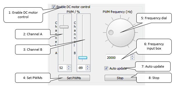
- Enable DC motor control – enables and disables DC motor control.
NOTE! Enabling or disabling DC motor control puts driver into stand-by to prevent sudden movement of motor or accidental overheating of stepped motor winding.
- Channel A – Slider and input box for PWM value for DC motor connected to output terminals A
- Channel B – Slider and input box for PWM value for DC motor connected to output terminals B
- Set PWMs – send new values to driver manually
- Frequency dial – set PWM frequency (period)
- Frequency input box – set PWM frequency (period)
- Auto update – send new values to driver automatically if checked
- Stop – sets PWMs to zero and put open collector inputs to high state enabling external PWM controller PWM control
NOTE! If driver is used in combination with external controller or BOB please make sure to zero PWM values by pressing button “Stop”. This way external controller takes over control of the PWM inputs again.
BINx driver control
In a BINx driver control mode the driver is set to be used alone just with two external buttons on pins BIN1 and BIN2 (please see subsection 4.5.1 – 6 pin PWM connector pinout for proper wiring). Connect NO button between pin BIN1 and GND. Connect NO button between pin BIN2 and GND. When BIN1 or BIN2 button is pressed motor moves number of steps defined in BIN1 and BIN2 steps respectively. Same motion profile is valid as in position control mode settings.
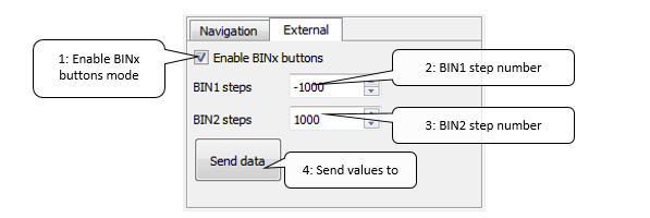
- Enable BINx buttons – when checked driver is in BINx buttons control mode
- BIN1 steps – Defines number of steps to move when BIN1 button pressed
- BIN2 steps – Defines number of steps to move when BIN2 button pressed
- Send data – send new values to driver
NOTE! Make sure to confirm the change of driver mode by clicking “Write values to driver”.
Log charts
PoStep60 application enables simple log of major driver parameter through time. By the chart the driver temperature can be monitored for possible overheating. This way driver setting can be adjusted or heat dissipation elements checked for its performance.
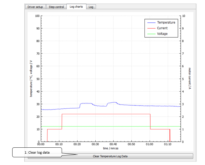
- Clear log data – Clears log charts data.
Firmware update
Application automatically checks for PoStep60 driver firmware version and advises when update needed. If by any chance automatic firmware update fails a manual update is possible. Please select “Firmware” tab and manually reset PoStep60driver to enter boot mode ie. when “Full update” button is enabled. Trigger update by pressing “Full update” and wait for finished update. After update the driver automatically resets and enters normal mode.
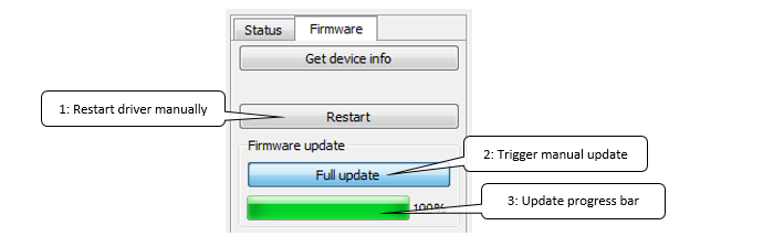
- Restart driver manually – trigger driver restart and enables the driver to enter boot mode.
- Full update – trigger start of full firmware update
- Update progress bar – shows status of update progress.
Major changes from 0.57 to 0.58:
- Voltage Too Low when disabled bug fix
- BINx mode – Button Up/Down control added
- I2C communication added
Major changes from 0.53 to 0.57:
- Predriver Fault bug fix
- Position control added
- DC motor mode setting added
- DC motor control added
- Improved Voltage and Temperature filtering
- Added installation notes (MS VS 2010 redistributable package)
PoStep60 I2C protocol specification
PoStep60 has implemented I2C communication connection which enables setup and read most of the driver configuration parameters and statuses. I2C pins are located on PoExtension connector (please see Figure 1).
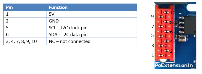
I2C address
PoStep60 default I2C address is set to 1 (0x01), but can be configured within PoStep60 application to any value between 1 and 127 (please see Figure 17). This way multiple PoStep60 drivers can be connected to same I2C bus and be monitored and configured externally in real-time. To confirm the I2C address “Write values to driver” has to be clicked.
PoStep60 I2C protocol
I2C communication is driven by a single I2C master which communicates to multiple slaves (PoStep60 drivers). Every packet consist of I2C address, Read/Write command bit, command byte (in case of write) and multiple data bytes. In write operation master specifies command for either write or read operation. In a Master read operation, based on previously written command, data bytes are sent back from PoStep60 driver (slave). Always applies the last command send by the master.
NOTE! In a Master read operation always applies the last command send by the master in a Master write operation. This way same parameter can be read continuously.
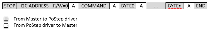
Master write
In Master write operation master always provide a command as a first data byte. Following bytes represent data to be interpreted by PoStep driver.
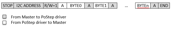
Master read
Before read operation we shall always perform a Master write operation providing command for read operation. After command is provided the Master read can be performed. In the Master read operation PoStep response with multiple bytes of data. The data has to be properly interpreted by the master.
PoStep60 I2C commands
0x01 – Loopback read
In a Master write operation master sends 0x01 command followed by 4 bytes. In a Master read operation the 4 bytes from previous write operation are send back from the PoStep driver. The main purpose of the command is to test a response of PoStep60 driver.
0x03 – Set Run/Sleep mode
To enable or disable (Run/Sleep) the driver Master shall write 0x03 command followed by one byte of data – BYTE0. BYTE0 relates to Run/Sleep mode as follows:
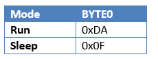
NOTE! Setting run over I2C overrides external enable signal. Similarly, external enable overrides internal sleep signal.
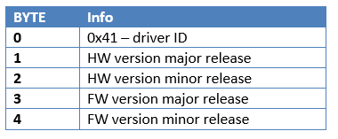
0x0A – Read HW/FW info
First Master writes 0x0A command (no data bytes are needed). In a next step Master reads 5 bytes of data where meaning of byte is described in a table below.
0x10 – Read voltage
To read PoStep supply voltage first Master writes 0x10 command (no data bytes are needed). In a next step Master reads two bytes of data. Calculated voltage is:
Voltage/V = (BYTE1 * 256 + BYTE0) * 0.072 = (BYTE1 << 8 | BYTE0) * 0.072
0x11 – Read temperature
To read PoStep temperature first Master writes 0x11 command (no data bytes are needed). In a next step Master reads two bytes of data. Calculated temperature is:
Temperature/ºC = (BYTE1 * 256 + BYTE0) * 0.0125 = (BYTE1 << 8 | BYTE0) * 0.125
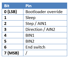
0x12 – Read pin statuses
First Master writes 0x12 command (no data bytes are needed). In a next step Master reads one byte of data. Each bit in the read byte represents one pin. 0 represents logic low level and 1 represents logic high.
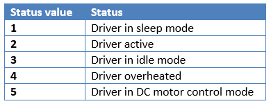
0x13 – Read driver status
First Master writes 0x13 command (no data bytes are needed). In a next step Master reads one byte of data. Read value represents driver status:
0x14 – Read driver mode
First Master writes 0x14 command (no data bytes are needed). In a next step Master reads one byte of data. Read value represents driver mode:
NOTE! Driver mode is read only value for I2C communication and can only be set by using USB connection and PoStep60 application!
0x20 – Read full scale current
To read PoStep full scale current first Master writes 0x20 command (no data bytes are needed). In a next step Master reads two bytes of data. Calculated current is:
current/A = 0.065*BYTE0 / (2BYTE1)
0x21 – Read idle current
First Master writes 0x21 command (no data bytes are needed). In a next step Master reads two bytes of data. Same formula applies as in subsection 8.3.9 0x20 – Read full scale current to calculate idle current value.
0x22 – Read overheat current
First Master writes 0x22 command (no data bytes are needed). In a next step Master reads two bytes of data. Same formula applies as in subsection 8.3.9 0x20 – Read full scale current to calculate overheat current.
0x23 – Read step mode
First Master writes 0x23 command (no data bytes are needed). In a next step Master reads one byte of data. Read value represents step mode:
Mode value = BYTE0 & 0x0F
0x24 – Read temperature limit
To read temperature limit first Master writes 0x24 command (no data bytes are needed). In a next step Master reads one byte of data. Calculated temperature is:
Temperature/ºC = BYTE0
0x25 – Read faults
First Master writes 0x25 command (no data bytes are needed). In a next step Master reads one byte of data. Each bit in the read byte represents one fault. 0 represents no faults and 1 represents fault occurred.
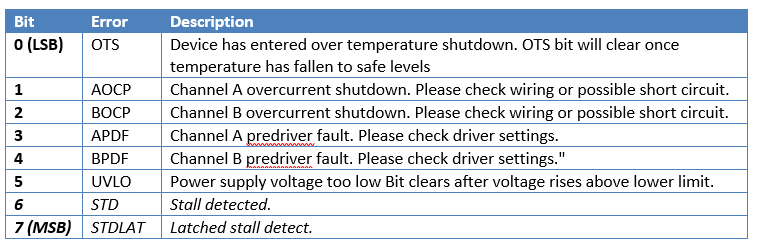
Fault 0 (OTS) cannot be cleared due to the nature of the fault. Faults 1 – 5 can be cleared and operation resumed by writing 0 to the bit location. Please see subsection 8.3.20 0x35 – Reset faults. Faults 6 and 7 are faults related to stall detection and are not real faults – they are not stopping operation of the PoStep60 driver. The faults 6 and 7 can be ignored.
NOTE! When there is no external power supply available the fault data shows 0xFF – all errors active! Please ignore the value while the power supply is not available.
0x30 – Set full scale current
Master writes 0x30 command followed by two bytes of data. BYTE0 and BYTE1 are calculated as follows:
int Tq = 123 * xxCurrent; //xxCurrent: current value in A
int Ai = 3;
while(Tq > 255){
Ai–;
Tq = Tq >> 1;
}
(uchar)BYTE0 = Tq;
(uchar)BYTE1 = Ai;
NOTE! Limiting values from subsection 6.1 – Electrical specification – limiting values applies.
0x31 – Set idle current
Master writes 0x31 command followed by two bytes of data. BYTE0 and BYTE1 are calculated using same algorithm as in subsection 8.3.15 0x30 – Set full scale current.
0x32 – Set overheat current
Master writes 0x32 command followed by two bytes of data. BYTE0 and BYTE1 are calculated using same algorithm as in subsection 8.3.15 0x30 – Set full scale current.
0x33 – Set step mode
Master writes 0x33 command followed by one byte of data – BYTE0. BYTE0 relates to step mode as follows:
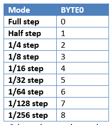
Other values are ignored.
0x34 – Set temperature limit
Master writes 0x34 command followed by one byte of data – BYTE0. BYTE0 is calculated as follows:
BYTE0 = Temperature/ºC
0x35 – Reset faults
To reset all faults Master shall write 0x35 command (no data bytes are needed).
0x3F – Write settings to EEPROM
To store changes made with any of the “Set” commands a Master shall write 0x3F command (no data bytes are needed).
Following commands are related to internal position controller – please see subsection 7.5 Position control.
0x40 – Read position
To read PoStep position first Master writes 0x40 command (no data bytes are needed). In a next step Master reads four bytes of data. Calculated position is:
position/steps = BYTE3 * 16777216 + BYTE2 * 65536 + BYTE1 * 256 + BYTE0 =
= BYTE3 << 24 | BYTE2 << 16 | BYTE1 << 8 | BYTE0
0x41 – Read maximal speed
To read PoStep maximal speed first Master writes 0x41 command (no data bytes are needed). In a next step Master reads two bytes of data. Calculated maximal speed is:
Maximal speed/steps/s = BYTE1 * 256 + BYTE0 = BYTE1 << 8 | BYTE0
0x42 – Read acceleration
To read PoStep acceleration first Master writes 0x42 command (no data bytes are needed). In a next step Master reads two bytes of data. Calculated acceleration is:
acceleration/steps/s2 = BYTE1 * 256 + BYTE0 = BYTE1 << 8 | BYTE0
0x43 – Read deceleration
To read PoStep deceleration first Master writes 0x43 command (no data bytes are needed). In a next step Master reads two bytes of data. Calculated deceleration is:
deceleration/steps/s2 = BYTE1 * 256 + BYTE0 = BYTE1 << 8 | BYTE0
NOTE! Set position and internal position control profile settings are applicable only when driver is in Position control or BINx buttons mode. To enable position control over I2C after reset and (in standalone mode) please enable BINx buttons mode and write values to driver.
To set required position of internal position controller Master writes 0x50 command followed by four bytes of data where:

0x51 – Set maximal speed
To set required maximal speed of internal position controller Master writes 0x51 command followed by two bytes of data where:

0x52 – Set acceleration
writes 0x52 command followed by two bytes of data where:

0x53 – Set deceleration
Master writes 0x53 command followed by two bytes of data where:

0x5E – Set zero
Master shall write 0x5E command (no data bytes are needed).
0x5F – Stop
Master shall write 0x5F command (no data bytes are needed).
Errata information
- I2C communication fails from time to time. Driver update is needed to a software version 0x0105 or above.
- Affected: All drivers with a software version bellow 0x0105.
- Predriver Fault bug causing faulty driver failure status. Driver update is needed to a software version 0x0103 or above.
- Affected: All drivers with a software version bellow 0x0103.
User manual changes
Changes in 5/12/2015 version:
- Fixed I2C communication breakage bug
- Added new I2C commands
Changes in 10/9/2015 version:
- Added BINx and I2C functionality related to application
- Added I2C protocol specifications and commands
- Added PoExtension pinout
Changes in 2/6/2015 version:
- 10 pin IDC connection diagram updated
- PWM input pinout description and note updated
Technical specifications section updated
1 Grant of license
The material contained in this release is licensed, not sold. PoLabs grants a license to the person who installs this software, subject to the conditions listed below.
1.1.1 Access
The licensee agrees to allow access to this software only to persons who have been informed of and agree to abide by these conditions.
1.1.2 Usage
The software in this release is for use only with PoLabs products or with data collected using PoLabs products.
1.1.3 Copyright
PoLabs claims the copyright of, and retains the rights to, all material (software, documents etc) contained in this release. You may copy and distribute the entire release in its original state, but must not copy individual items within the release other than for backup purposes.
1.1.4 Liability
PoLabs and its agents shall not be liable for any loss or damage, howsoever caused, related to the use of PoLabs equipment or software, unless excluded by statute.
1.1.5 Fitness for purpose
No two applications are the same, so PoLabs cannot guarantee that its equipment or software is suitable for a given application. It is therefore the user’s responsibility to ensure that the product is suitable for the user’s application.
1.1.6 Mission Critical applications
Because the software runs on a computer that may be running other software products, and may be subject to interference from these other products, this license specifically excludes usage in ‘mission critical’ applications, for example life support systems.
1.1.7 Viruses
This software was continuously monitored for viruses during production; however the user is responsible for virus checking the software once it is installed.
1.1.8 Support
No software is ever error-free, but if you are unsatisfied with the performance of this software, please contact our technical support staff, who will try to fix the problem within a reasonable time.
1.1.9 Upgrades
We provide upgrades, free of charge, from our web site at www.planet-cnc.com, www.poscope.com. We reserve the right to charge for updates or replacements sent out on physical media.
1.1.10 Trademarks
Windows is a registered trademark of Microsoft Corporation. PoStep, PoDDS, PoRef, PoScope, PoLabs and others are internationally registered trademarks.
Support:
- Stepper motor driver – explanation
- Homing sensor
- Plasma voltage divider
- Bipolar stepper motor driver – PoStep25-256
- PCB tester – PoStep25-256
- plasma cutter troubleshooting guide
- CNC plasma floating head
- plasma cutting equipment
Related Posts