Oscilloscope probe compensation is a procedure to reduce impact of probes on measured signal. We will show that on our Mega50 USB oscilloscope from our measurement instruments.
We have to keep in mind that oscilloscope probes aren’t just pieces of wire with pointy end attached to them. Here are two important aspects to consider when selecting and using probe:
- Faithfully transmit the signal from your device under test to the oscilloscope
- Do not disturb! meaning you want to select a probe that changes the signal at the test point as little as possible
Loading effect
Even oscilloscope probes have their respective transfer characteristics which can have great impact on measured signal. The unintentional interaction of the probe and oscilloscope with the circuit being tested is called circuit loading. To minimize circuit loading, you will probably use a 10X attenuator (passive) probe. The 10x attenuator probe minimizes circuit loading and is an excellent general-purpose passive probe. Circuit loading becomes more pronounced at higher frequencies, so be sure to use this type of probe when measuring signals above 5 kHz. The 10X attenuator probe improves the accuracy of your measurements, but it also reduces the amplitude of the signal seen on the screen by a factor of 10. However probes don’t introduce only resistive load but also capacitive.
In parallel with the probe’s input resistance you have the compensation capacitor. When buying a probe, you should pay attention that the capacitor’s value can match the value of scope’s input capacitance.
Basically the oscilloscope input front-end has its own internal capacitance and its own internal resistance. In order to prevent signal distortion, the capacitance of the probe needs to match the capacitance of the scope. If R1C1 = R2C2, then this circuit has the amazing result that the effect of both capacitors exactly cancel.
Probe capacitance is usally adjustable because the probe doesn’t know the exact capacitance of the particular scope it is connected to.
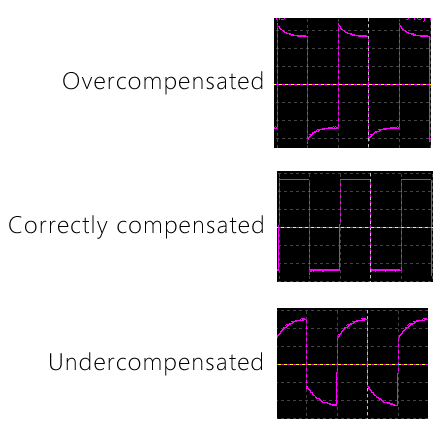
If the probe isn’t well matched with the oscilloscope, you’ll get overshooting or undershooting. On the image below you can see this effect when changing probe capacitance.
Oscilloscope probe compensation
To maximize the bandwidth of an attenuating probe, the probe capacitor must be adjusted precisely such that the input capacitance of the scope is canceled. This is accomplished by a procedure known as compensation. The scope probe is connected to a square wave source called the calibrator which is built into the scope. The probe is then adjusted to make the square wave as square and flat topped as possible and your oscilloscope probe will be correctly compensated.
Probe compensation with Mega50 oscilloscope
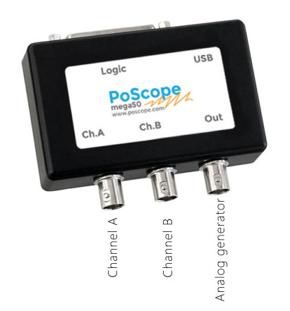
Oscilloscope probe compensation with Mega50 is really simple. Mega50 has two analog inputs and one analog output for signal generator purposes. This offers us to provide test signal for the compensation procedure.
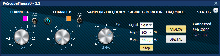
Let’s start PoScope4 application and let’s configure Mega50. First we need to configure output signal. We choose square with maximum available amplitude and frequency 1kHz. Let’s press start button to enable signal generator output. This will be our test signal. Now let’s configure analog input(s). We will use only one input and it’s up to you which one you prefer. There is no difference in terms of input resistance and capacitance therfore any of it will be good. Since we will be compensating probe at ratio 10:1 the input signal will be 10 times lower than original signal. For that case we set channel input range to 0,2V or 0,5V. Sampling frequency is set at 15MHz.
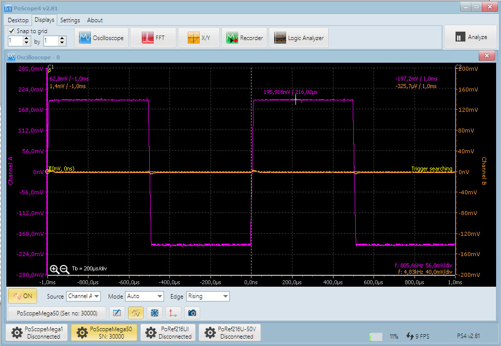
Now let’s connect probe to channel A and probe tip to analog output. Open oscilloscope display in the PoScope4 and set timebase to 200us/div and trigger with settings as on image below.
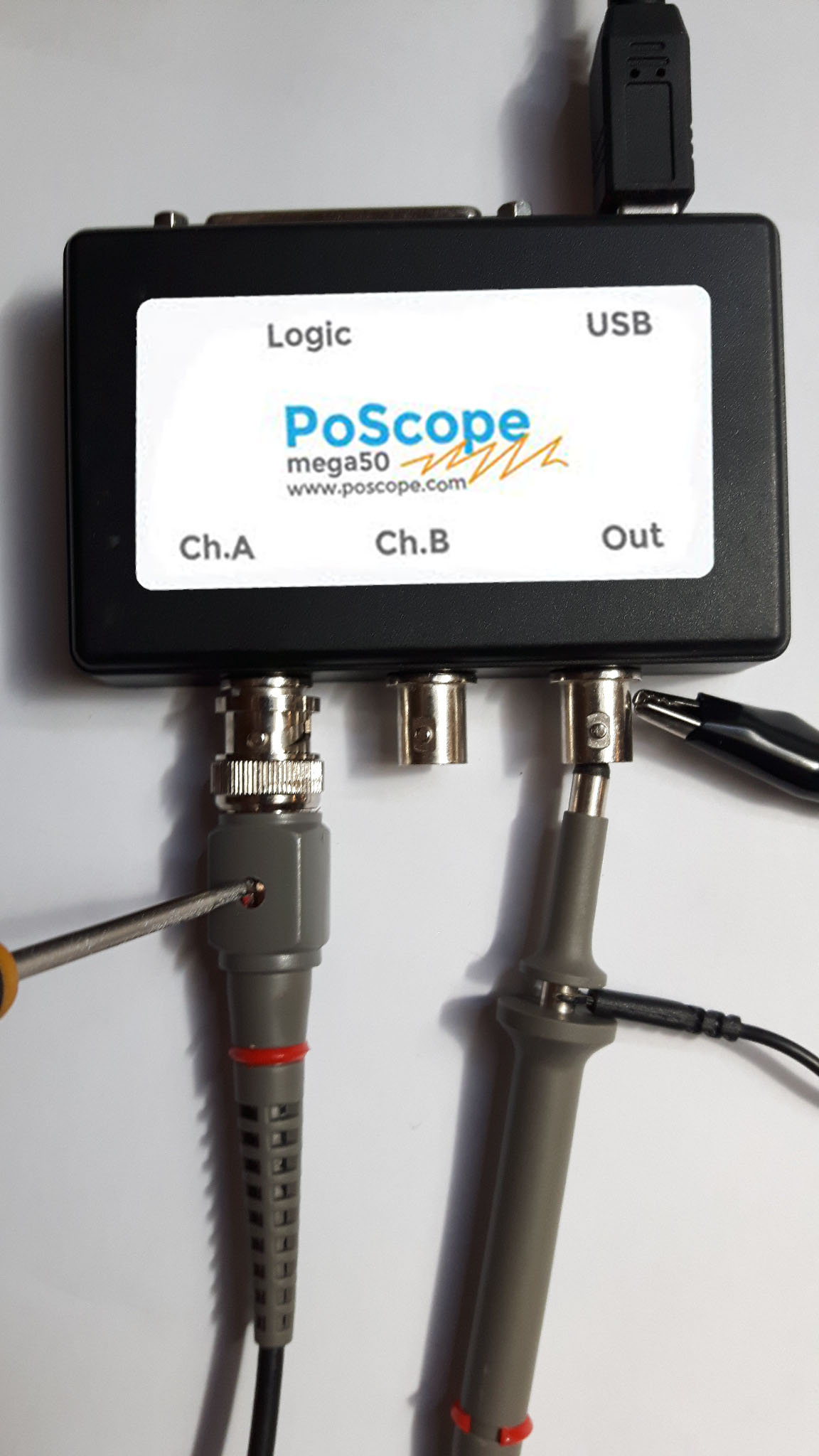
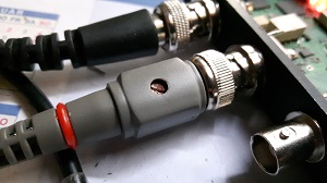
Now change the capacitor value with the screw driver. Some probes has extra box at the connector side with screw – trimmer capacitor. Location of trimmer capacitor may vary with different probe manufacturer.
You should observe signal on oscilloscope display and set up capacitor until you see proper square signal as on image below. In that case your probe is correctly compensated. You can repeat the process for all probes you intend to use with Mega50.
Conclusion
As you could see oscilloscope probe compensation procedure is easy and fast. If you have different oscilloscopes it’s standard procedure before starting measuring. So the net result is a probe and scope input combination that has a much wider bandwidth than the 1:1 probe, due to the effective cancellation of the two capacitors. The penalty that is incurred is the loss of voltage. The oscilloscope now sees only one-tenth of the original voltage (hence the name 10:1 probe). Also notice that the circuit being measured sees a load impedance of R1 + R2 = 10 MOhm, which is much higher than with the 1:1 probe. Some probes are designed to be conveniently switched between 1:1 and 10:1 operation. Many oscilloscopes can detect whether you are using a 1X or 10X probe and adjust their screen readouts accordingly. However with some oscilloscopes, you must set the type of probe you are using or read from the proper 1X or 10X marking on the volts/div control.
- Stepper motor driver
- Stepper motor driver-complete exlanation
- USB CNC Controller-PoKeys57CNC
- Homing sensor-PoHome1IRNPN
- Bipolar stepper motor driver – PoStep25-256
- PCB tester – PoStep25-256
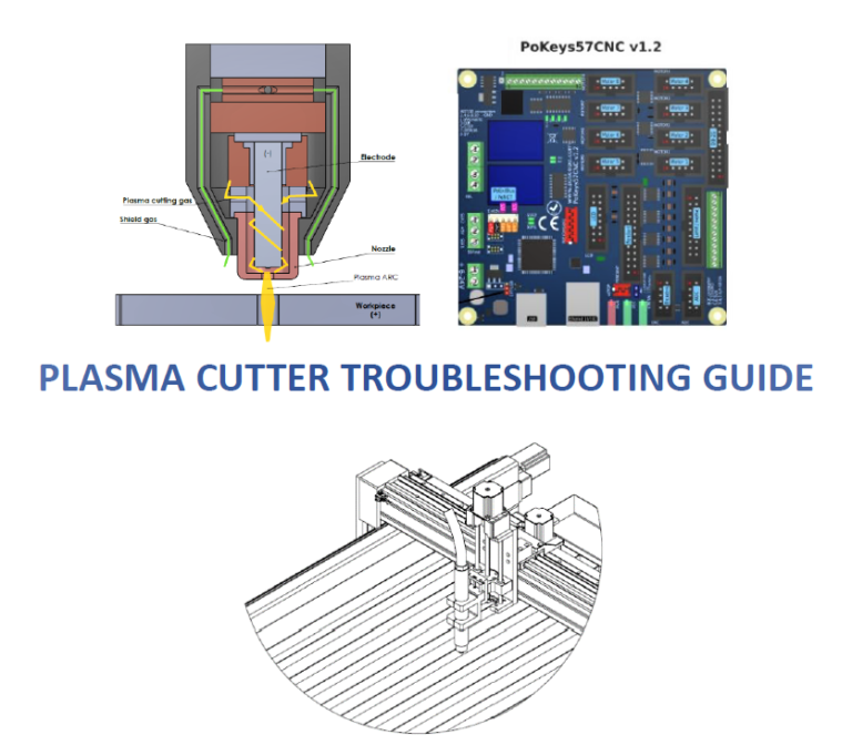
- Plasma cutter troubleshooting guide
- CNC plasma floating head
Related Posts