We are beginning the list of customer projects with Ian’s model railway automation using USB I/O controller devices. Here is the presentation of the project by Ian H.
Model railway automation – Terminus station
I’m building a fairly large model railway and I have a special interest in signaling. Although the signaling will be manual, semaphore signaling, I wanted to create a PC-controlled entrance/exit (NX) panel for the terminus station. The PC would need to control points, signals, power sections, and isolation sections. Photo 1 shows the layout plan and photo 2 shows how the terminus station has been divided up into power sections and isolation sections. Each power section can be controlled by 1,2 or 3 relays. Each isolation section is controlled by one relay.


A view of the terminus station can be seen in photo 3.

A database stores all of the information that appears on the mimic diagram – photo 4, including the control board and relay numbers.

A Delphi program communicates with the database and drives the control panel.
All of the points, signals, etc would require relays and drivers. I would also need to be able to read whether a point had moved correctly to set up a route. Therefore I needed a device that would interface to a PC and provide discrete inputs and discrete outputs. Lots of them! All of the devices I researched on the internet had a very limited number of channels until I found the Pokeys 56U/57U
I have 5 interface boards (so far!) and each of them is similar to the one in photo 5. The Pokeys57U board is connected to the PC through a USB hub. Each Pokeys board has been programmed with the number of the board it is situated on. The green wires coming into the top of the Pokeys57U are the switch inputs from the point motors. These indicate which position the point is set to. The red wires from the Pokeys57U are all outputs and these go to Darlington Transistor Arrays which then drive the relays. The relays with mainly orange wires are single pole relays which drive power sections and isolation sections. The 4 relays on the right are double pole relays and these operate the point motors.

Programming the Pokeys57U has been simple and reliable. A Delphi type library is supplied by Polabs and this is imported into the project. It’s then a matter of importing the board number and relay number from the database and then either reading the input or driving the output. Writing the panel software and loading the database with all of the combinations of routes, point,s signals and zones will take a bit longer.
Thanks to Polabs for producing a really neat piece of kit
Ian
If you need electronics for your automation and other project here are some our products:
- Stepper motor driver
- Stepper motor driver-complete explanation
- USB CNC Controller-PoKeys57CNC
- Homing sensor-PoHome1IRNPN
- Bipolar stepper motor driver – PoStep25-256
- Plasma cutter troubleshooting guide
- CNC plasma floating head
- PCB tester – PoStep25-256
Related Posts

We present a new version of our graphical programming tool...
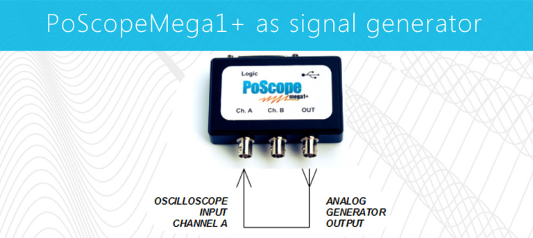
PoScopeMega1+ as signal generator
Remark: There are two versions of PoscopeMega1....