Metal dance pad is another project by our customer that uses PoKeys57U. Let’s let Gal describe it. Original post was published on http://e.pavlin.si/2016/06/02/metal-dance-pad-with-load-cell-sensors/
Metal dance pad with load cell sensors
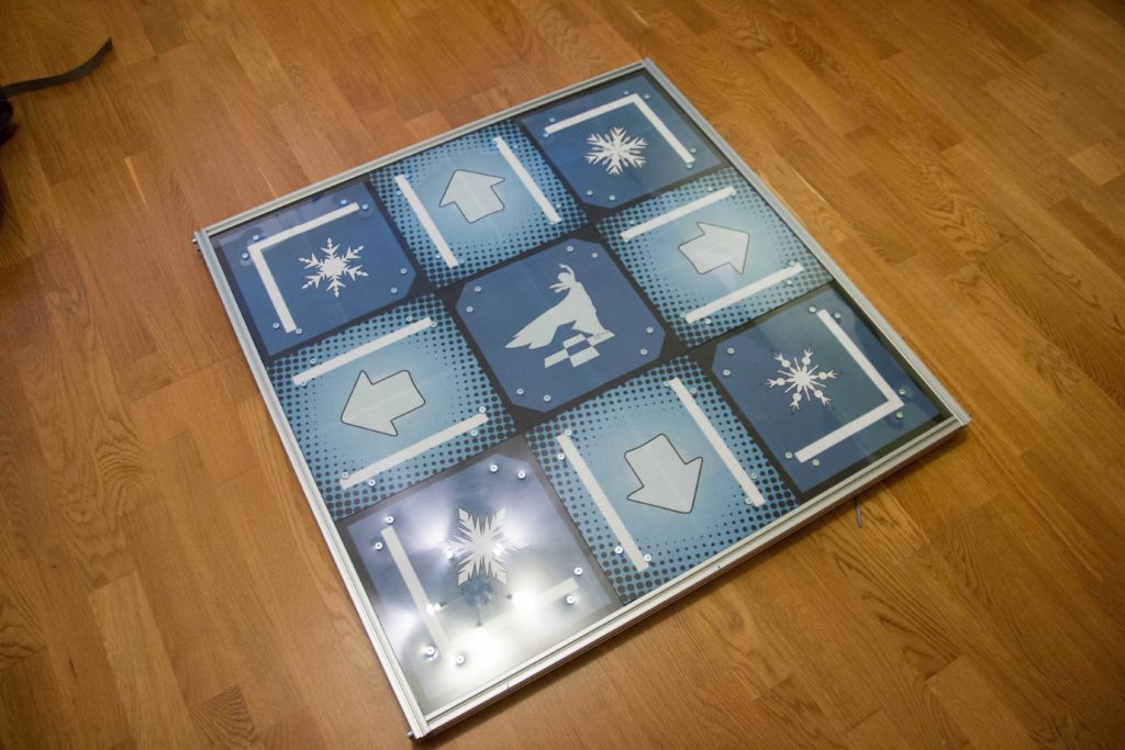
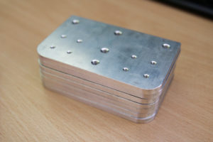
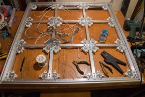
Finished pad
What happens one a man has too much time and a workshop with fancy toys in his garage? With school being too easy and girlfriend nowhere to be found I often find myself exploring areas that interest me. It started with drones, electric powered bikes and longboards but for the last month I often found myself dancing. Firstly, I borrowed my friend’s softmat which was okay for the beginning but soon I progressed with my dancing skills and started to hate everything about it. I’m sure all DDR dancers know what I’m talking about. That’s when I decided to build one.
Enough about me. ????
Thorough research was required to figure out how dance pads even work. After collecting a lot of great ideas and learning about their weaknesses and advantages I wrote down the following desired goals of the design:
- zero noise,
- high sensitivity,
- low mechanical wear,
- and LEDs on each pad.
At this point I had pretty much everything sorted out. Load cell sensors were my choice because they promised long life and no noise. Pads are basically a sandwich of plywood, polycarbonate plastics on top and LEDs in the middle. Main frame is made with aluminum profile normally used in machine frame constructions.
After that I spent about one week designing everything in CAD software, ordering parts and learning about load cell sensors. I also designed first prototype of electronics required for converting low voltage signals (1 mV) from sensors to more useful 5V that any USB module can read.
Maybe you’re wondering why I made everything so complicated? Why do I need 36 sensors, special electronics, CNC machine and a 3D printer to make this pad? Don’t ask, because I don’t know. I want to expose that making this pad simple and easy to build for everyone wasn’t my priority. I took it more as a proof of concept and something to learn on and expand my knowledge in designing and manufacturing electronics. From this aspect the dance pad was a great success.
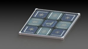
Computer render of the dance pad
So everything designed with a beautiful picture on my monitor. What’s next? To the hardware store!
3D MODELS AND DESIGN FILES
I wanna play with the 3D model of your dance pad!
If you have Acrobat Reader (it will not work in other PDF viewers) you can try to open the 3D pdf. It contains exploded view of my dance pad.
http://gal.pavlin.si/lol/pad-assembly.PDF
That’s just a preview. Pfffff. I want the real thing!
I am more than happy to give them away as they are necessary for building this complex thing but you should also know they are licensed under CC license. Read licence.txt and readme.txt file for more information.
http://gal.pavlin.si/dance/pad.zip
MAIN FRAME
After gathering few kilograms of aluminum I soon began assembling first pieces. Center cross made from 20x20mm square tubes is surrounded by 4 20x40mm profiles.
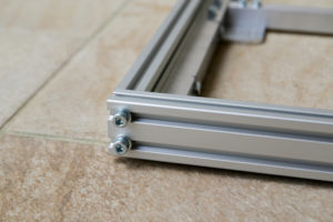
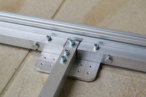
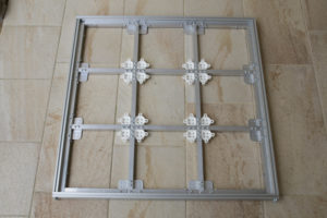
On the bottom side you can see CNC machined plates that hold everything together including white parts which are sensor mounts. Square tubes are fastened in place with 9 M5 screws and 3d printed plastic sensor mounts with M3. Side square tubes are mounted with M6 screws (hex head) and nuts in T slot of the outer frame.

SENSORS
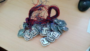
50 kg load cell – 36 of them
Sensors are pretty common 50kg load cells normally used in digital body scales. Each cell consists of two resistors that vary their resistance proportional to applied force. Resistance of one goes up and second down when force is applied. There are 4 sensors under each pressure plate located in its corners. Even distribution of force is achieved that way, however, sensors are wired in such way that force distribution doesn’t matter because (simply put) signals from each sensor add up in one summed signal. Mechanical characteristics of sensors also define maximum load on each square. With 4 50 kg sensors that is 200 kg per pad. More than enough for 70 kg guy like me but someone bigger could be hitting the red zone during jumps when fast decelerations are higher than 1G.
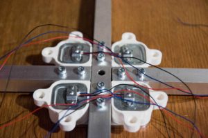
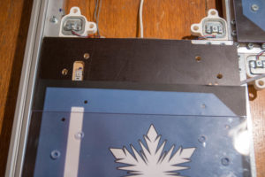
Four sensors that belong to 4 different pressure plates
If you want to know more about sensors, take a look at Electronics section.
WIRING
It took far too much time to wire everything up. I made small circuit boards to solder thin sensor wires on and keep them in place. I used M3 double sided adhesive tape to stick those tiny board to frame. For connection between electronics and sensors four wire shielded cable was used. Further information is available in Electronics section.
PRESSURE PLATES
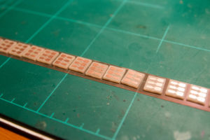
Like I mentioned before each pad consists of sandwiched plywood, clear polycarbonate plastic and RGB LED strip. Art printed on standard paper is under clear plastic. Top screw holes were countersinked to hide heads of screws. Eight M5 screws are required for each square. Screws go in the holes of white parts and create some kind of linear bearings. If you want to know exactly how it’s made, take a look in my CAD files.

Square shaped plywood sheets are highly modified to fit LED strips inside. Corners of squares were also made thinner to make space for screws of the frame. After some tests I found out that plywood is too thin and bends too much. That was fixed with few aluminum profiles on the bottom of each plate. This could also be fixed by using thicker plywood or some other material in the first place.
ELECTRONICS
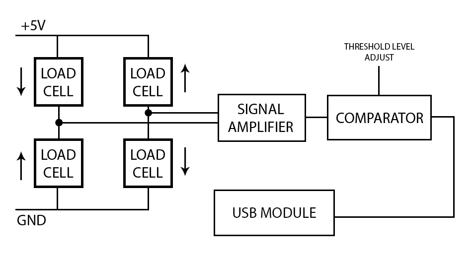
Here’s the electrical schematics of 4 load cells in a Wheatstone bridge outputting differential voltage across OUT1 and OUT2. Arrows show where resistance goes with load on the sensor. You can see that with no pressure applied the bridge is balanced. Once pressure is applied differential voltage signal rises because of differences between potentials in OUT1 and OUT2.

Problems:
- Signals are weak. I got 4 mV with around 700 N of force across 4 sensors. This can be solved with a proper amplifier.
- Sensors are not paired. This means that with no force applied output signal is NOT zero. This can be solved with a multiturn potentiometer.
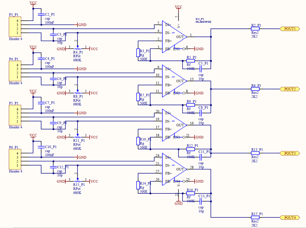
Schematics of my circuit are shown below. I used a ISL28470FAZ which is a quad instrumentation amplifier. Because I need 5V or 0V on the output, I used high gain to make the amplifier work almost as a comparator. Balancing the bridge is achieved with 1.5 MOhm (in schematic they are 680k) multiturn potentiometers (R4,8,11,15) with tab connected to one of the sensor outputs. There is a 10 pF capacitor (C5,8,11,13) in parallel with the closed loop resistor (R5,9,12,16) to reduce high frequency noise. Decoupling capacitors are also placed in parallel with bridge’s supply and between outputs of the bridge. Once again to reduce noise. P3,4,5,6 are connectors for load cell bridge, where pin 4 is positive supply, 3 is ground, 2 is OUT2 and 1 is OUT1.
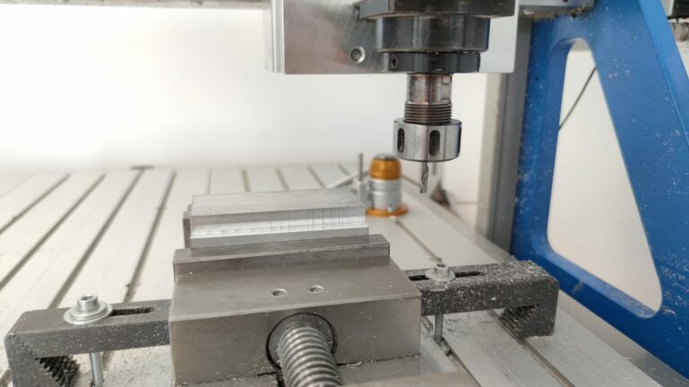
I made the circuit board with my CNC machine. It is double sided with 10 mils min clearance and 12 mils min track width.
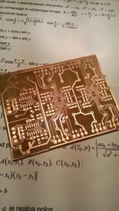
First circuit board
That’s how I got 5V or 0V signals. Then I had to get them to my PC.
PoKeys56U
PoKeys56U USB module is largely used for emulators. It supports graphical programming which makes it super easy to use. It can also emulate joystick and keyboard. Setup was extremely straightforward and I got it working in under 15 minutes. The whole dance pad, except LEDs, is powered by +5V from USB.
Note: PoKeys56U is an outdated version. Current version is PoKeys57U or PoKeys57E (with ethernet).
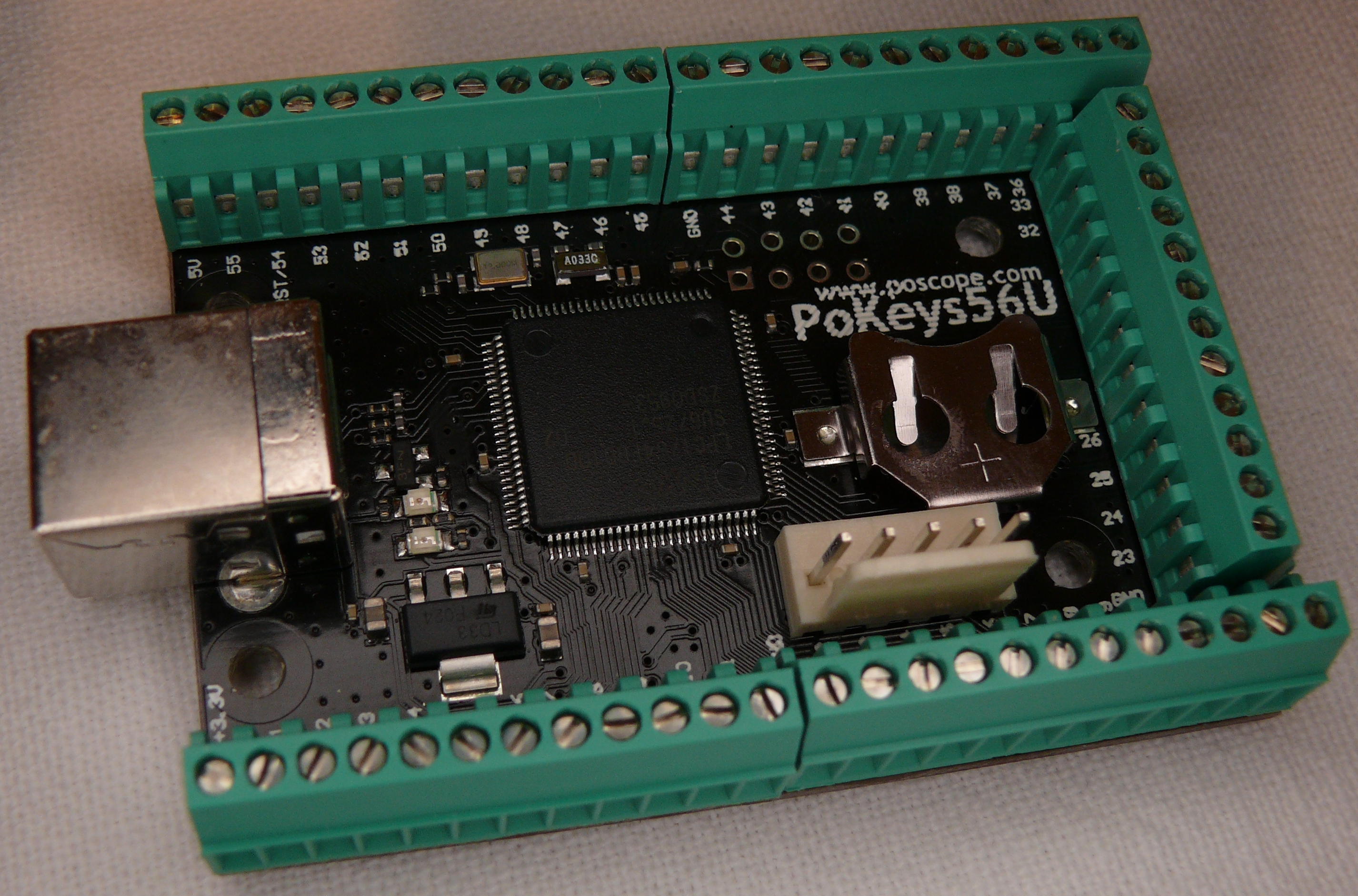
PoKeys56U by Polabs
PoKeys56U is a simple, easy-to-use USB device with a lot of features making it powerful input/output device. It is highly adjustable and requires no complex knowledge on device programming (it supports graphic programming). All peripherals can be tested inside the software in monitor mode.
It is evident from the diagram that the USB module supports many input/output devices such as 1-wire sensors, LCD, encoders, etc. I only used digital inputs that were mapped to virtual joystick, digital output for switching LEDs and 3 PWM pins for the colour of the LEDs. In total I used 9 pins for input, 8 for output and another 3 for PWM. 20 in total.
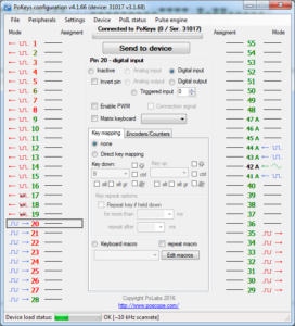
PoKeys – Windows GUI for mapping pins
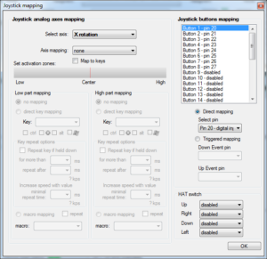
PoKeys virtual joystick – windows GUI
I think you realised by now you can make almost any USB input device with PoKeys. It even supports a matrix keyboard! But what I like the most about this module lies in another piece of software called PoBlocks. PoBlocks is a piece of software that enables programming of PoKeys devices. Programs for controlling LEDs are “written” or made with graphic programming. Here’s how the program and software look in monitor mode:
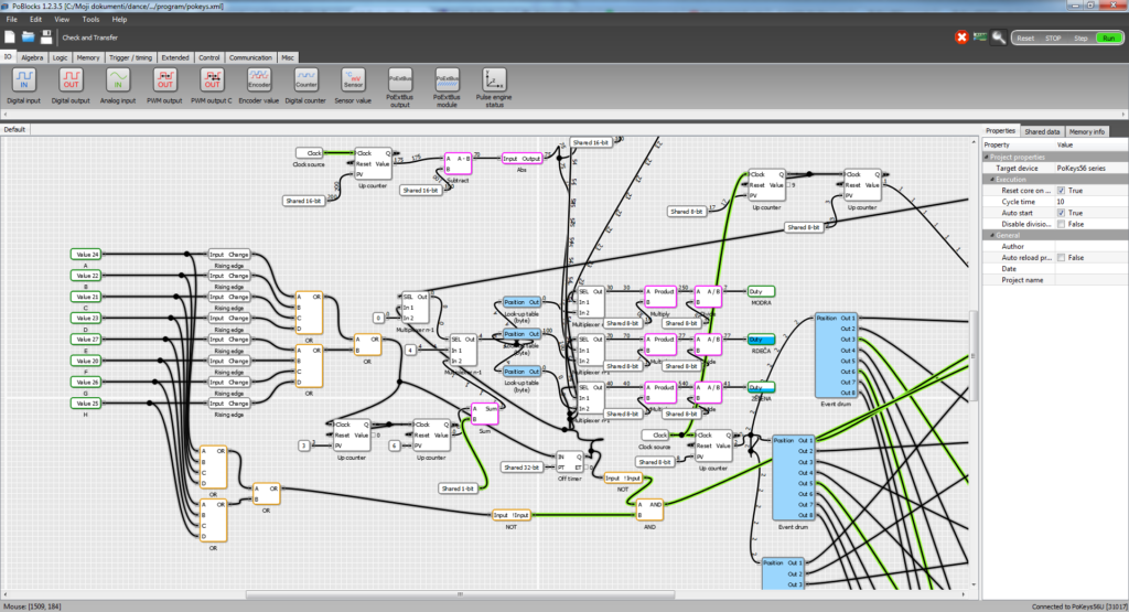
PoBlocks in monitor mode
Whole program didn’t fit on the screen. Here’s what it does:
- Each square lights up when it’s stepped on
- 4 steps on either square change colour of the whole pad
- When square is down for more than 4s it starts blinking red (used as indicator for faulty sensors)
- Idle mode:
- Circling motion
- Blinking
- Colour fading
CONCLUSION
I hope this post gave you some new ideas. The concept was proven to be functional and comparable to others. I wouldn’t recommend building this thing to anyone because it’s not the simplest design out there. It is also work in progress with possible improvements everywhere. If you have a question or want to contribute to this project you can write a message below.
Also if you need an informations about Polabs – Pokeys products, here are some useful links:
Related Posts