In this blog we will introduce how to use stepper motor driver with modbus communication. A practical example will answer any questions you may have about PoStep60 programmable stepper motor controller.
What will we try to achieve?
Programmable stepper motor controller PoStep60-256 using Modbus
Our plan is to read few driver's parameters and make some stepper motor movements using a Postep60 Modbus commands described in PoStep60 user's manual.
Table of Contents
Modbus programmable stepper motor controller – HW
- An Arduino board. We will use Arduino Mega 2560.
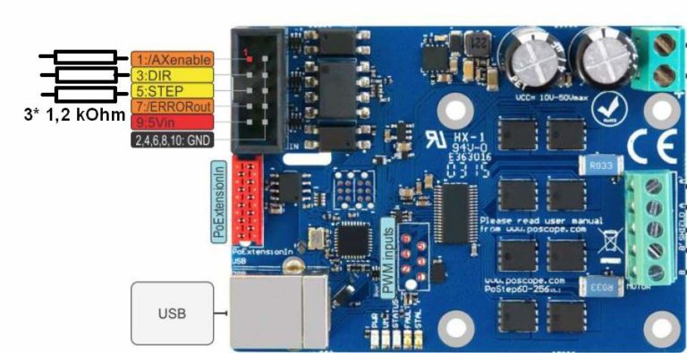
- Stepper motor driver with modbus communication: PoStep60-256 with the latest firmware update (version 1.20 or newer) that can be free downloaded from product page.
- An adapter board with differential bus transceiver. We will simply use chip SN65176BD.
- Optional, Uart (RS232) to USB converter (PoUSB12)
- And of course an stepper motor and DC power supply. In our case stepper motor Nema-17 and switching power supply PoPower 12-25
OK, let’s start!
How are stepper motors controlled
Stepper motor needs a driver circuit that generates for the stepper motor useful signals. However, the driver must provide a voltage on motor winding in the right time sequence and direction, to create the necessary magnetic force to move the axis. We know simple drivers for which jumpers can be controlled the amperage. We also have more advanced ones, which can be set in addition to the already mentioned parameter also micro-stepping, speed, acceleration, decay time, different operating modes, etc. One of a kind is undoubtedly PoStep60. Even more, the programmable stepper motor controller has three serial communication protocols with which we can configure the controller.
One of them is Modbus. Modbus is one of the standard industrial communications protocols, mostly used with PLCs.
Stepper motor driver – Modbus peripheral
First, we will prepare peripheral. PoStep60-256 stepper motor driver with Modbus communication uses Modbus RTU protocol over RS485 transmission lines. That’s why we need to prepare the adapter board to connect it to Arduino’s UART port.
We will use a differential bus transceiver SN65176BD from TI and connect it as follows:
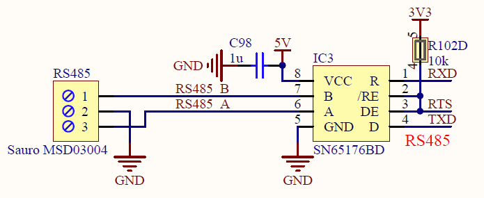
Modbus communication over RS485 -adapter circuit schema
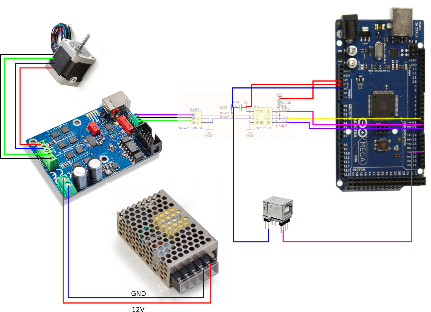
After that we do the connection of the entire HW as shown in picture bellow. Don’t forget plugged the main AC power (110/ 230VAC) to power supply module. See the connection diagram below.
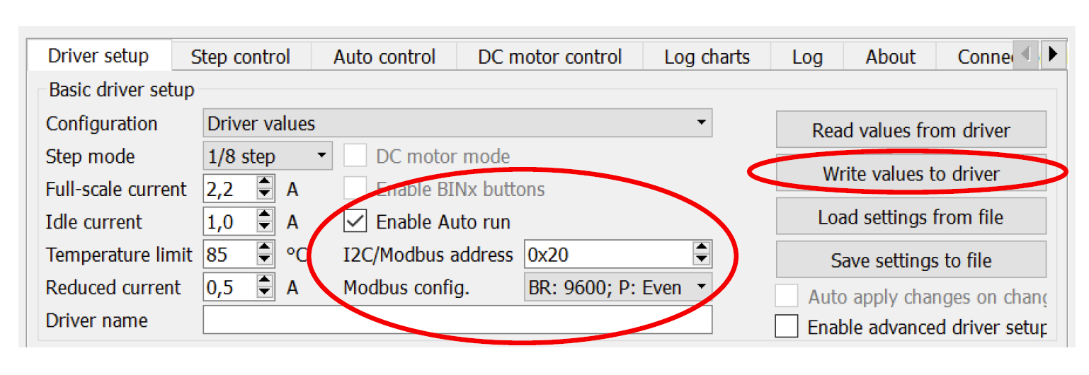
The next step is configure the Postep60-265 programmable motor driver. We do that in PoStep60v1.20 application.
- Use USB cable to connect with the PoStep60-256.
- Run the PoStep60_v1.20 .exe and in a Driver setup tab select “Enable auto run” and set Modbus address and configuration. In our case we will set address to “0x20” and choose “BR: 9600; P: Even” configuration.
At the end we write values to driver! So, now we had set the driver.
Stepper motor driver – Modbus – Arduino example:
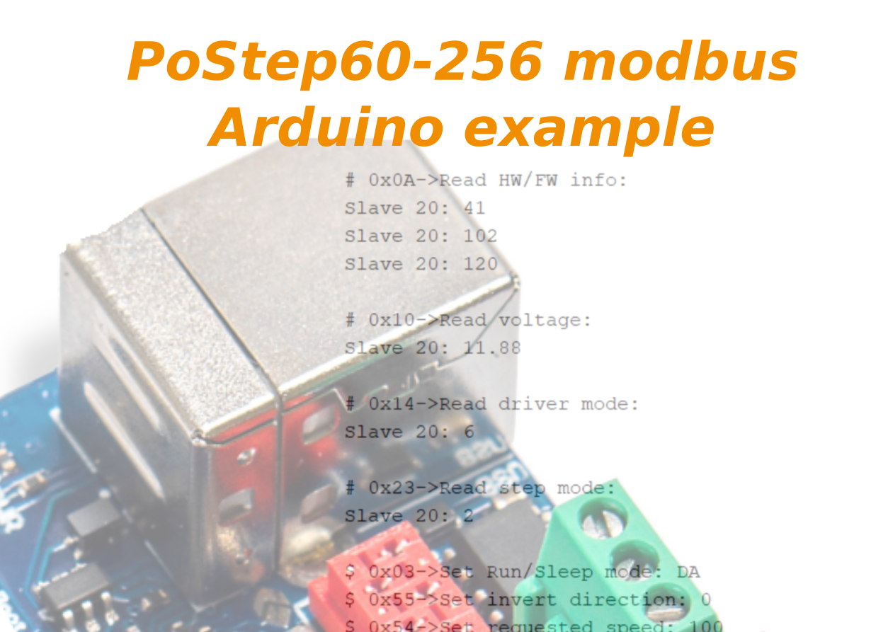
For the demo PoStep60-256 ModbusRtu over RS485 communication, we will first download the Modbus_DEMO_PoStep60.ino file from the PoStep60-256 product page. The application uses a library <ArduinoModbus.h>.
However, the Modbus serial port must have an address, baud rate, and parity set as we set the driver in PoStep60v1.20 application described above. We use “Serial1” for a print terminal port with BR 9600 and no parity check.
ModbusRTUClient.begin(9600, SERIAL_8E1);
Serial1.begin(9600,SERIAL_8N1);
We had done all the work. Compile the code and load it to your Arduino board.
Application demonstrates:
- reading driver’s HW/FW info, voltage, mode and step mode
- driving a stepper motor with different speeds in both direction using commands: Run/Sleep(0x03), invert direction(0x55) and set requested speed(0x54)

To run the demo again, please reset the Arduino board.
Also, try testing other Postep60 Modbus commands using the following functions:
 PoStepModbusRead(int Rd_command, int slaveID)
 PoStepModbusWrite(int Wr_command, int slaveID, int command1, int command2, int command3)
Please read the PoStep60 user manual for detailed information about commands.
Other programmable stepper motor controller PoStep60 features
To sum up, the PoStep60-256 stepper motor driver allows users to choose from three different communication protocols we described in the user’s manual :
- USB protocol used with the free downloadable application or using API to use with your own app
- I2C protocol affordable with Arduino, Raspberry Pi or similar boards
- Modbus protocol used in industrial automatization
- Stand alone with step direction signals
You can read more about USB protocol and how to use API with motor driver in this blog post.
Other
Please also check our latest blog posts and products. It can help you to improve your machines or get some ideas on how to even make them better.
- Bipolar stepper motor driver – PoStep25-256
- Plasma voltage divider
- PoKeys57CNC -USB CNC Controller
- Torch height Controller – THC
- Homing sensor
- 4th axis for CNC router
- Introduction to CNC hardware – electronics
- Plasma cutting equipment
- What is CNC plasma cutting
- CNC Plasma floating head
- Plasma cutter troubleshooting guide
Related Posts