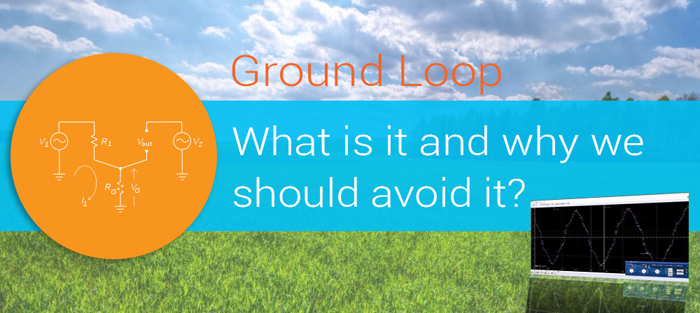
Ground loop is a result of electricity flowing to a ground over two or more paths.
Ground loop is usually generated by connecting together different power sources. Users in many cases believe that all ground points are at the same potential. That is far from the truth. All wires or other conductors have a resistance or when we talk about AC conditions, impedance. Even if this impedance is exceptionally small and precisely because of that it can generate relative high currents induced by magnetic field. This currents causes voltage drops, which can be treated as noise sources. Therefore we should avoid ground loops.
 Simplified ground loop circuit
Typical example of ground loop noise is a 50/60Hz hum in audio system. A listener hears it like an irritating sound in a speaker.
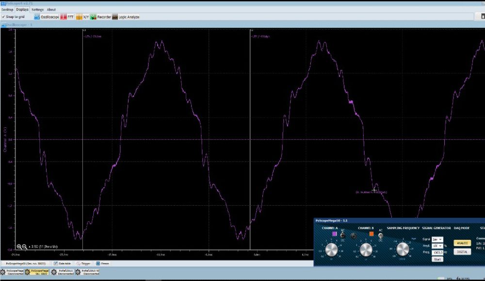
50Hz hum signal, captured with PoScope4
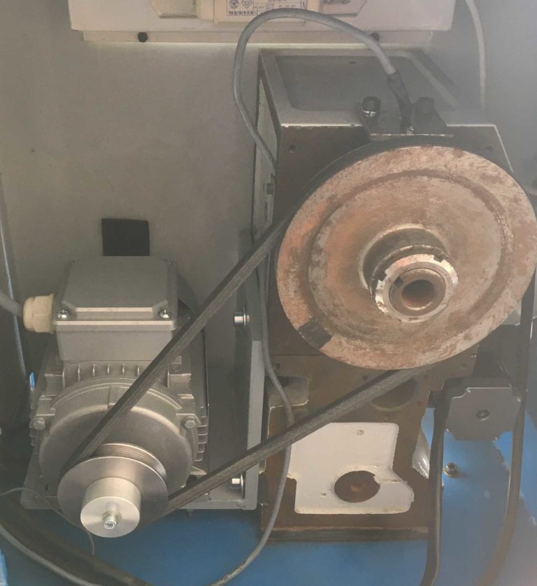
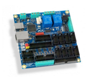
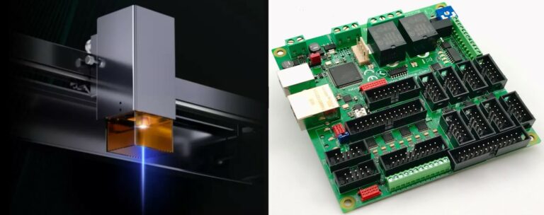
Another example is a CNC controller circuit or stepper motor driver used for CNC Machine motors. In such environments EMF disturbance level can be quite high. Consequently, induced currents bad shielded communication cables can cause malfunctions in CNC Machine operation.
It doesn’t matter whether we talking about low or high power, analog or digital world, high or low frequencies, ground loop can give a HW developer a rough time. In other words, the good PCB or system ground design is essential for stable performance without interruptions and errors.
More informations about stepper motor driver: compete explanation- stepper motor driver.
And finally…How to avoid it?
In some cases breaking the ground loop would fix the problem. But be aware! Never disconnect the ground from an AC plug! It’s potentially dangerous and can cause an electrical shock!
You can find many articles about ground loops and techniques how to avoid them. In general, there is a guideline for HW designers that can be summarized in several main points:
- use star topology for ground distribution
- use balanced interconnection
- separate power and data lines
- keep power part circuits closer to source ground
- use differential signals and isolators
- the cable shield should be grounded only at one end
And how can device users make sure to prevent ground loop? We can try to resolve the issue by carefully connecting system parts using isolated transformers, optical connections, RS232, RS485 or USB isolators and etc. We write about the USB isolator in one of the previous posts.
Remember: no electrical connections no ground loops!
Please also check our latest blog posts and products. It can help you to improve your machines or get some ideas on how to even make them better.
- Plasma voltage divider
- Bipolar stepper motor driver – PoStep25-256
- PCB tester – PoStep25-256
- USB CNC Controller – PoKeys57CNC
- Torch height controller – THC
- homing sensor
- 4th axis for CNC
- Introduction to CNC hardware – electronics
- plasma cutting equipment
- what is CNC plasma cutting
- CNC plasma floating head
- Plasma cutter troubleshooting guide
Related Posts