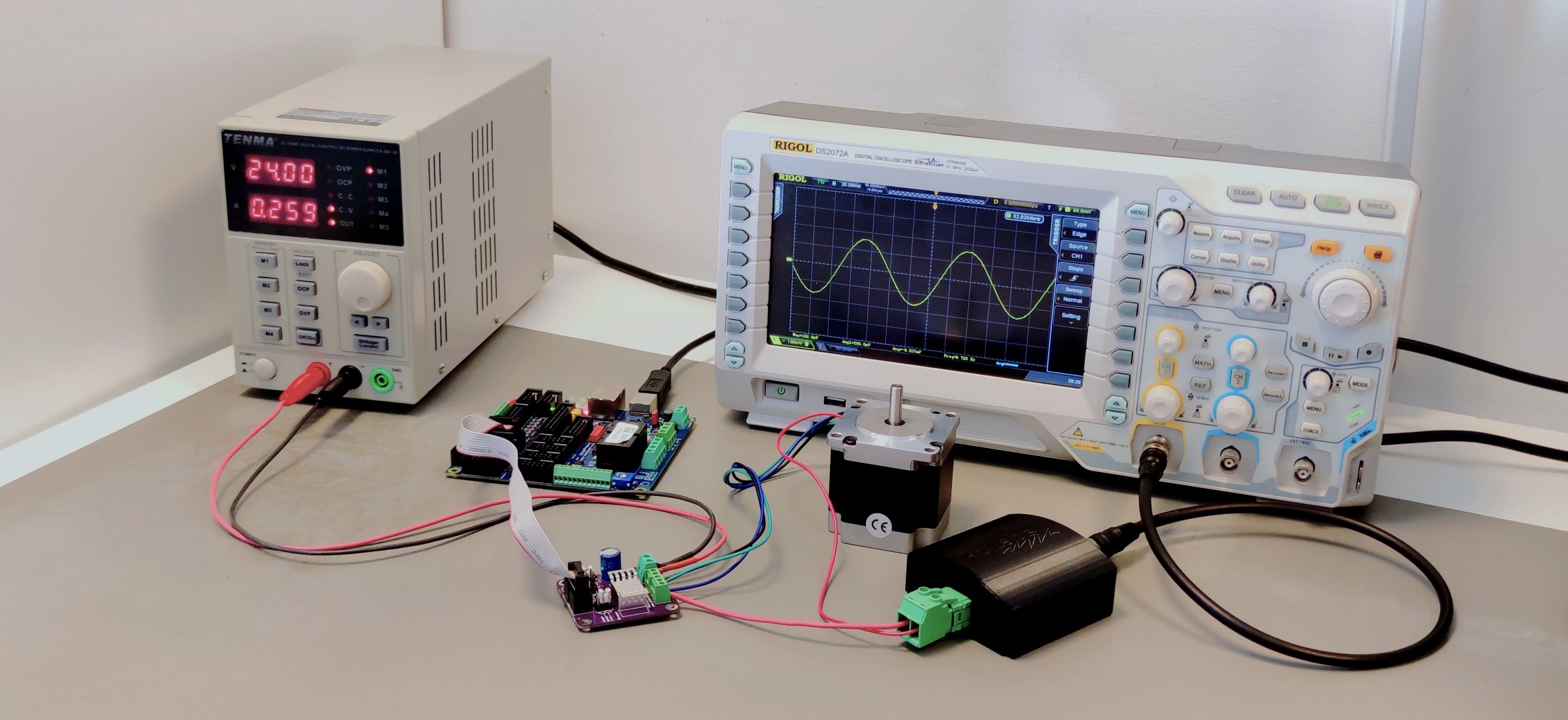
Yes, you can measure current with oscilloscope and current measurement with oscillsocope does not only tell you the instantaneous value of the current but gives you the time changing waveform from which the operation of the device can be observed. Time changing currents can be measured and displayed on the oscilloscope with help of the oscilloscope current probe.
Table of Contents
What tool do I need to measure current with oscilloscope?
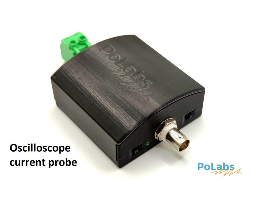
Oscilloscope current probe or current sensor is device, that is used to measure current flowing through it. It can be then displayed on the oscilloscope. For measuring sinusoidal current and getting the RMS value of current, ordinary multimeter is usually enough. But if you are interested in observing the shape of the current of particular transient event, waveform through the motor or any other kind of time varying current you need to do current measurement with oscilloscope and current probe and multimeter is not enaugh.
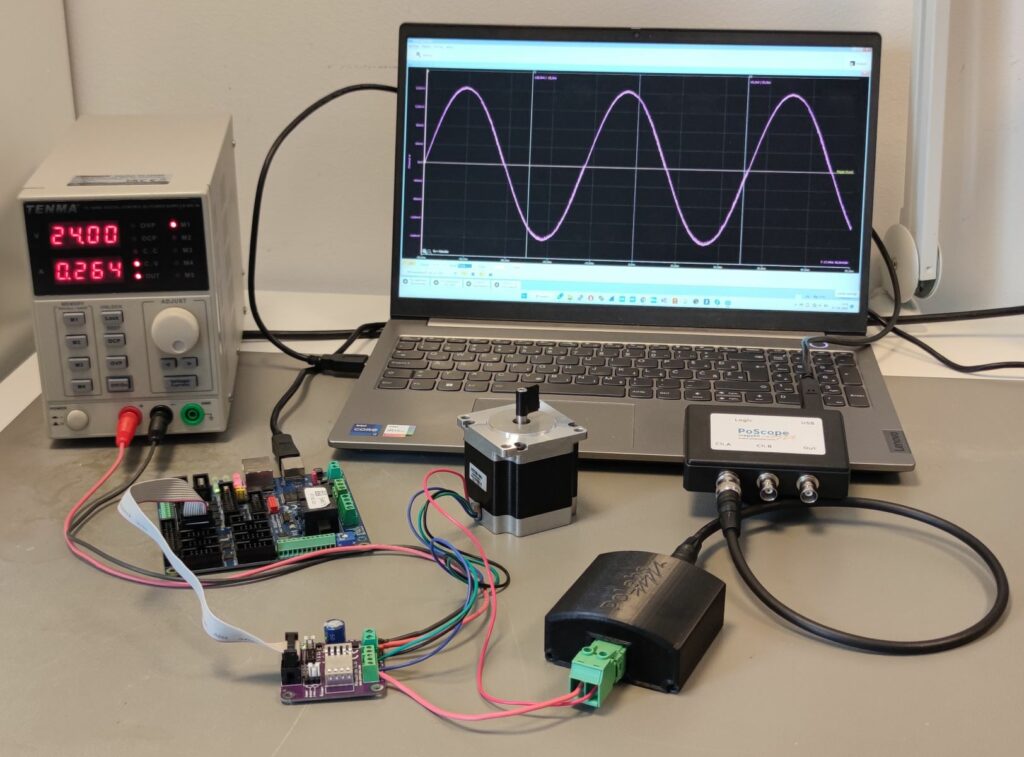
Current probes usually do not alter the operation of the device or circuit under test. The current probe is connected to the oscilloscope or other data aquisition system to record and display the waveform. User can then perform the analysis of the current measurements with oscilloscope and learn a lot about the device that is tested and it’s performance and operation.
Types of probes for current measurement with oscilloscope
There are AC and AC/DC current probes. The AC measuring family of current probes rely on the principle of electromagnetic induction. Magnetic field, that is generated around the conductor with alternating current induces the currents in the probe and voltage is generated on the resistor. The problem with such measurements is that current can not be DC and need to have a minimal frequency and the DC offset can also not be measured.
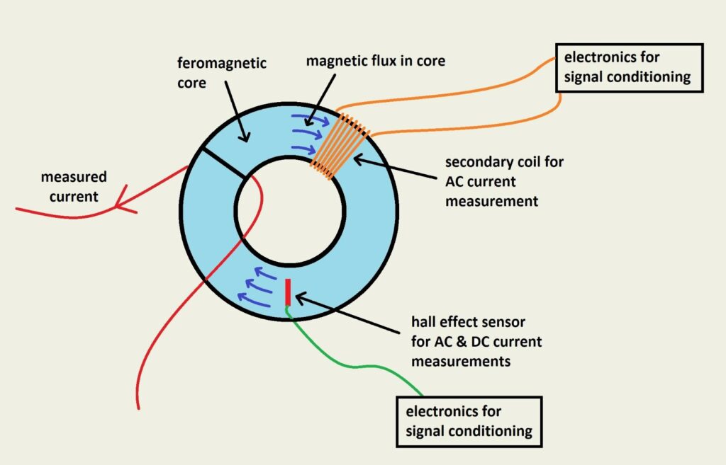
The AC/DC current probes on the other hand can measure direct currents (DC) also. They work on the different principle with hall effect sensors instead of induction. Hall effect sensors can also detect direct currents where induction does not occur. They measure the magnetic flux (field) directly and with that, all the information about the current can be acquired.
Hall effect is the phenomenon that occurs, when that magnetic field alters the path of electrons in conductor and small voltage appears between two points which is called hall voltage. It is proportional to the current in the measured conductor and so with the proper signal conditioning in the hall effect current sensor we can get the output signal voltage that is proportional to the measured current.
How to connect current probe and measure current?
The current probes are generally clamped across the conductor in which we are measuring current. That means that the current measurement with oscilloscope is easier since you do not need to alter any wiring in the device under test. But the clamp-on current probes still have some disadvantages. Among others are:
- Limited frequency response (they can not accurately measure high frequencies usually above 10-20 kHz)
- Non linearity (voltage representation of the current is not linear across the whole range)
- Susceptibility to external fields (external fields can introduce noise or distortion in the measurement)
- Calibration (they need frequent calibration to ensure accuracy)
- Size (they are usually very bulky and heavy)
- Cost (Clamp-on current probes are usually quite expensive)
Our solution to the above mentioned challenges is the CurrentSens oscilloscope current probe. It is professional measurement instrument for measuring currents from 5 A to 25 A RMS. The bandwidth is the crucial advantage of our instrument since the upper frequency limit is 200 kHz and if for factor 10 higher than the similar probes. It also has better linearity and accuracy.
CurrentSens specifications:
- Current range from 5 A to 25 A RMS
- 200 kHz bandwidth
- AC and DC current measurement
- Linearity of 0.1%
- Accuracy of 0.7%
- Measure on voltages up to 450V RMS
- Powered by two AA or NiMh cells
- Selectable voltage reference
How current is represented when performing measurement with oscilloscope?
When performing current measurements with oscilloscope the measured current is represented with voltage. Since the relation between current and output voltage is proportional, we have a factor with which the current is represented. It is called sensitivity of the current probe. That factor tells us how much voltage we get on the output for every ampere of measured current. Higher the number, the better is the resolution. But for measuring higher values of current, the sensitivity is usually lower since the limited output voltage has to represent the whole range of current.
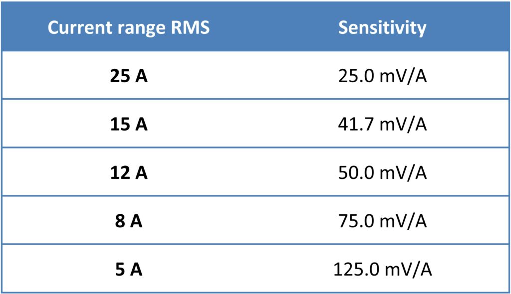
As visible from the table the higher current range is traded for lower sensitivity. CurrentSens oscilloscope current probe can measure currents in both directions. One way to display that current then is to reference the zero current from 0 V output voltage so the current flowing in negative direction is displayed as negative voltage. That is useful for measurements with oscilloscope where it is immediately visible when the current changes the direction.

But if you want to measure currents with instruments that do not accept negative voltages or ADC-s you want to have zero current in the middle of the output voltage range so you can measure in both directions with positive voltages. Since the output voltage of the CurrentSens is 5 V, you can select the reference voltage to be at 2.5 V for the zero ampere current. So when the current changes direction the output voltage falls below the 2.5 V.
Since the connector for current is galvanically isolated from the measuring side, so it is safe to measure on voltages up to 450 V RMS. Please practice safety precautions when measuring and dealing with high voltages.
About
Polabs is developing and manufacturing electronic products for many different areas and needs and also developed some machines to make work easier, more productive, and higher quality. Below, here you can find some latest blog posts and products:
Check also:
1. Measuring current with oscilloscope
2. How to measure current with oscilloscope
