PoStep60-256 microstep stepper driver can also operate with 24 V control signals.
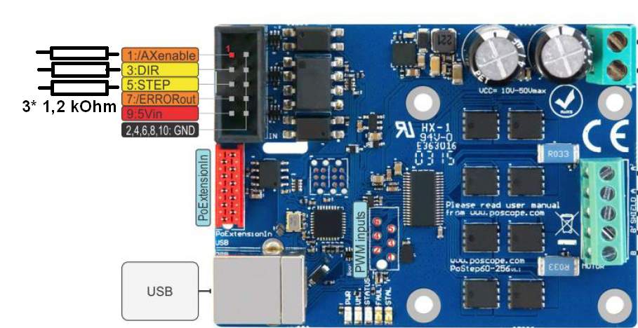
PoStep60-256 microstep stepper motor driver (stepper motor driver wiring) is normally operating on 5V inputs for step, direction and enable signals. Most industrial PLC controllers provide only 24V signals. However, adding a simple 1,2 kOhm resistor in series with control input will make the PoStep60-256 micro-stepping stepper motor driver compatible with 24V industrial standard.
You need only 3 pieces of 1.2kohm resitors for one Postep60-256 stepper motor driver wiring. Any size will work as long as their value is 1.2 kOhm and they are available in almost every electronics shop.
Also, check our products, It can help you to improve your machines or get some ideas how to even make it better:
- USB CNC CONTROLLER-PoKeys57CNC
- Homing sensor-PoHome1IRNPN
- Bipolar stepper motor driver – PoStep25-256
- PCB tester – PoStep25-256
- Plasma voltage divider
- 4th axis for CNC
- Introduction to CNC hardware – electronics
- Plasma cutting equipment
- what is CNC plasma cutting
- what is a CNC plasma floating head
- plasma cutter troubleshooting guide
Related Posts

In modern CNC systems, flexibility in connecting control interfaces is...
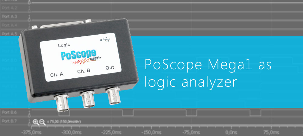
Logic analyzer is an electronic measurement instrument, capable of capturing...
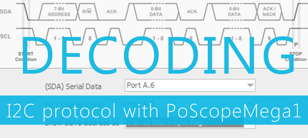
Decoding I2C protocol
Inter–integrated circuit (I2C) simplifies the hardware part of...