In this PoBlocks tutorial, we will describe how PoBlocks can be used to solve a stepper motor positioning task. PoBlocks is a graphical programming tool for PoKeys device and is free of charge for PoKeys users.
Background
We have been approached by one of our users on how a positioning system can be implemented using PoBlocks, avoiding the need for a PC. The task is to generate 10 moves (each of 2.000 stepper motor steps) in one direction, then move the motor back to the initial position. The following sketch illustrates what is required. Here is compete explanation about stepper motor driver.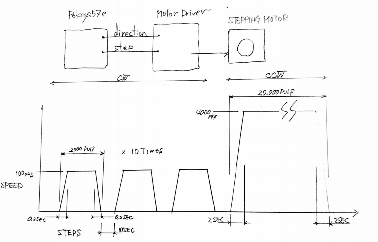
So, each move should be of exactly 2.000 steps (pulses) at 100 steps/s with acceleration and deceleration of 500 steps/s/s. After the move, the motor needs to be stationary for 10 seconds. This needs to be repeated 10 times.
In the end, the motor should move 20.000 steps back to the beginning at 4.000 steps/s and acceleration and deceleration of 2.000 steps/s/s.
For the purpose of this tutorial, we reduced all times by a factor of 10, using forward move velocity of 1.000 steps/s (acceleration of 5.000 steps/s/s) and return move velocity of 40.000 steps/s (acceleration of 20.000 steps/s/s).
Solution
The solution can be divided into initialization of the pulse engine, cycle triggering, forward cycle and return move. Let’s go through all these steps one by one.
Initializing pulse engine
Before Pulse engine can be used, we need to initialize it. Although this can be done using the PoKeys configuration application, we will add it into the PoBlocks project to make the PoBlocks project self-contained.
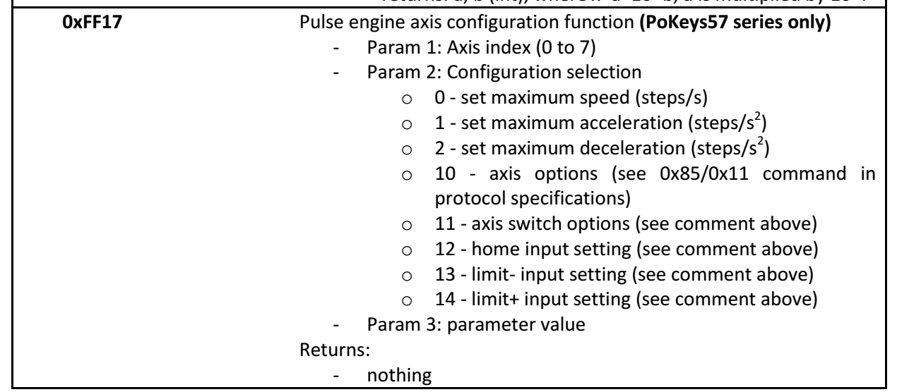
To implement the requested motion, we need the position-based motion planner in the Pulse engine functionality of the PoKeys device. Additionally, we need to limit the maximum speed, acceleration and deceleration. Let’s take a look at the Pulse engine axis configuration options (as specified in the PoKeys protocol specification document).
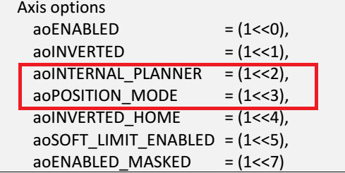
PoKeys pulse engine can operate in different modes with default mode being so called buffer mode, where the exact motion trajectory is specified and generated elsewhere. In this mode, PoKeys executes the motion that is defined for each individual 1 ms time slot. This mode is used when PoKeys generates motion, generated by the PC-based CNC software (Mach3/Mach4). For the task in this tutorial, we will need the motion planner in the PoKeys device to generate the motion and we need this planner to move the stepper motor to exact position. Therefore, we need to set the flags aoINTERNAL_PLANNER (bit 2) and aoPOSITION_MODE (bit 3). In the figure above, the (1<<2) notation is left shift operation from C-based programming languages and indicates the bit 2 (similarly, (1<<3) indicates bit 3). The setting for our axis is therefore (1<<2) + (1<<3) = 4 + 8 = 12.
Since Pulse engine functionality has not been implemented in PoBlocks as a dedicated block, we will need to use the custom PoIL code block to initialize the pulse engine. This block allows us to insert the raw PoIL code into the PoBlocks diagram, giving us the access to internal functionality of the PoIL interpreter in the device. The Pulse engine is configured with the help of system calls and registers. These are described in the PoIL.pdf document, which is automatically installed in the PoKeys installation folder (C:\Program Files\PoLabs\PoKeys\ by default).
In order to configure the axis with the correct settings, we need to write the value 12 to the appropriate register (PoIL document specifies these – 0x990 is the axis configuration register for first axis, 0x991 is the axis configuration register for the second axis etc.

So, let’s configure axes 1, 2 and 3 with internal motion planner in position mode by loading the value of 12 into working register, then storing it to the byte register at addresses h0990 (h indicates the hexadecimal value), h0991 and h0992 (this is done in lines 12-15). Then, let’s put the Pulse engine into normal running state (value of 3 – see protocol specification document on valid Pulse engine states) by storing the value 3 to register h0980 (Pulse engine state register).
Executing the lines 12-19 will therefore configure axes 1,2 and 3 in internal motion controller in position mode and activate the pulse engine operation. Let’s add a command to move the pulse engine axis position to 0 (move the attached stepper motor to initial position) by storing the value of 0 to 32-bit (Double-word) register h920 (Reference position).
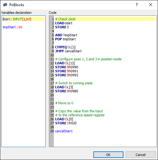
Let’s take a look at what other lines in this block do. Since the configuration is something that gets triggered on certain events (it does not execute continuously), we need to make sure that we only do it when it is required. The first six lines do exactly that. The value of the start signal (which is defined as the first input on the left side) is first loaded and immediately stored to the stack (for later use). Then the logical AND operation is done over the value of start (still residing in working register W) and the inverted value of the tmpStart variable (previous value of the start input and also defined in the left side). The result of the operation is logical 1 (true) if tmpStart is 0 and start is 1 (transition from 0 to 1) – it is stored in the working register. We now pop the value from stack (start signal value we pushed to the stack before) and store it to the tmpStart without affecting the working register. The value if working register is then compared with (literal / constant) value of 1 and if the result of the operation is negative (logical false), the execution jumps using the JMPF to cancelStart label at the end of the code. Similarly, JMPT instead of JMPF would make the execution jump if the result of the previous operation would be position (logical true).
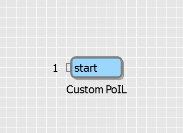
The resulting block can now be put somewhere in the PoBlocks project – since we need to execute it only once, we can just wire a constant value of 1 to it. Since all variables are initialized to 0 in PoBlocks by default, this will make the code we created to execute only once in the first iteration.
Cycle triggering
We will now focus on creating 10 cycles with the specified timing constraints. We need to activate a move of 2.000 pulses, wait 2 seconds for the motion to execute, then pause for 1 second before starting the next move. Once 10 moves are executed, a returning move must be started.
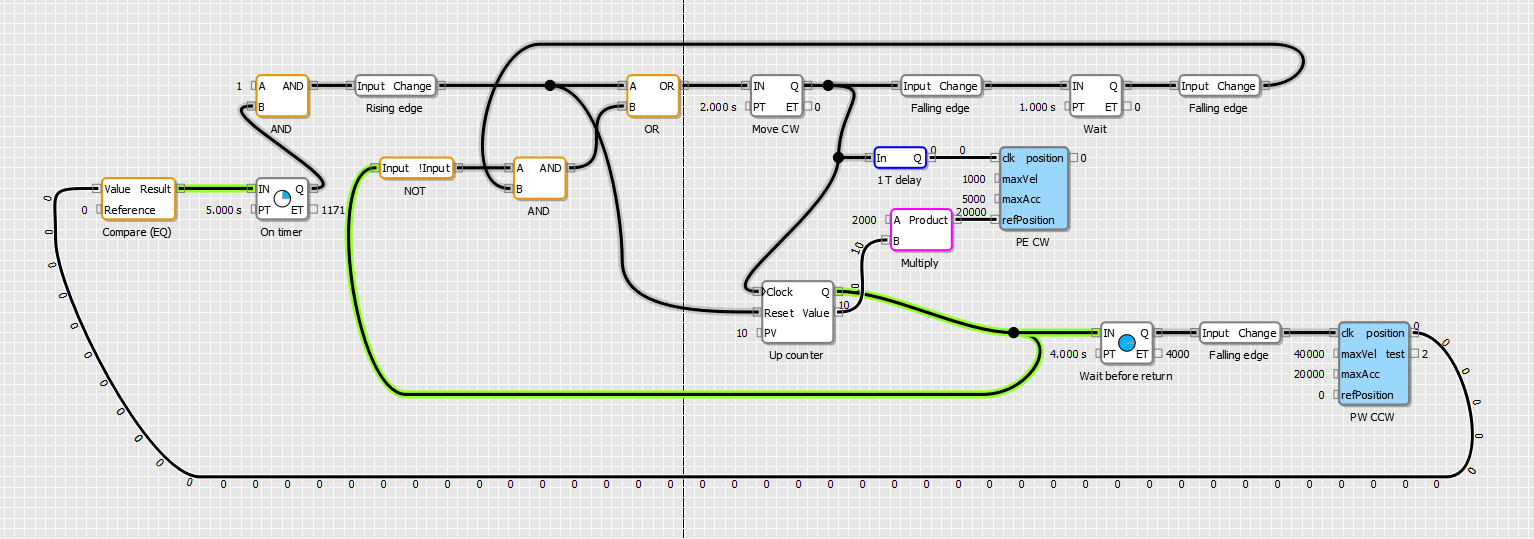
So, let’s take a look at how we implemented this
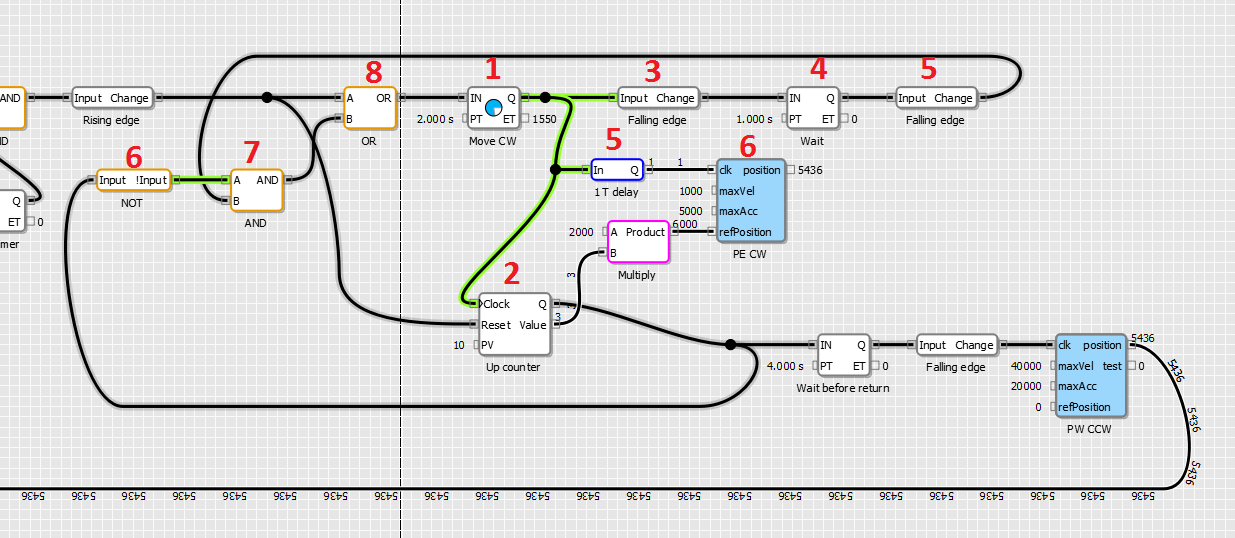
Block 1 (Pulse timer): when this timer is triggered by block 8, it generates a pulse of predefined length (2 seconds in this case). Generated pulse increments the counter 2, which counts the move cycles and determines the reference position (the value of the counter is multiplied with 2000 to generate a reference position). The pulse also triggers block 6 (clockwise motion command to Pulse engine) via ‘1 T delay’ block. We need the delay here because we want the block 6 to use the new (incremented) value of the counter (block 2) as a reference. The delay block delays the signal for one cycle (defined in the PoBlocks project settings, 10 ms by default).
Block 3 (falling edge): this block triggers the block 4 when the pulse of the block 1 (lasting for 2 seconds) turns off. This should happen in parallel to the pulse engine axis position reaching the reference position. This generates a one second pulse using another Pulse timer block 4. The end of this pulse triggers the block 7 via another falling edge detector (block 5).
Block 6: output of this block signals whether we have generated 10 moves or not – once the counter block 2 counts to 10, its Q output will activate, in turn make the block 6 to output switch off. The block 7 therefore is used to block any additional moves to be generated once 10 moves are done.
Block 8 is used to combine the manual start cycle command signal with the output of block 7 (which is activated once cycles 1 to 9 are complete).
Forward cycle
Let’s take a look at another Custom PoIL block (blue blocks) – PE CW in the diagram. The first few lines are identical to the lines we saw before – we want to trigger the operation on certain events (on the clk input). Then, there are three calls to the system function 0xFF17, which we will take a look more closely.
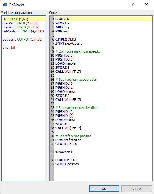
In order to configure the axis motion parameters, we need to call the system function 0xFF17 as described in the PoIL document. The first value on the stack will indicate the axis we want the motion parameter to be set. The second value on the stack tells the function, which motion parameter we want to change. The third value on the stack will contain the value of the parameter. In the code above, we load three values to the stack (using PUSH or STORE S instructions), then call the function 0xFF17 using the CALL WL[hFF17]. Let me explain how this works – PoIL processor in the PoKeys device uses 16-bit instruction addresses and the instruction CALL tells the processor to jump to a certain position in the instruction memory. Therefore, we specified a Word (16-bit) constant (Literal) with the hexadecimal value of FF17.
The last few lines of the block set the reference position (as we have done already before in the initialization code) and output the current axis position to output ‘position’ using the lines 35 and 36.
Note that the labels used in the code (cancelStart:, skipAction1 etc.) are all inserted into the same PoIL project code. When using custom PoIL blocks, make sure that each block has uniquely defined labels. PoLabs is planning to address this in the future upgrade of the PoBlocks.
Return move
The following diagram displays the complete solution (except for the initialization block). As the counter counts to 10, its Q signal not only blocks the execution of the next forward cycle, but also triggers another Pulse timer, which starts the return move after 4 seconds. The return move command block uses the same code as forward move block we just examined, but has a fixed reference position of 0.
Output of this block is then connected to a compare block – once the axis position reaches initial position (position 0), another timer (On timer) restarts the whole cycle by resetting the counter and instructing the first move.
Final words
See the video of the stepper motor moving here
This tutorial should give PoKeys users an insight into the usage possibilities for the PoBlocks tool and PoKeys devices. Feel free to download the PoBlocks project below and test it on your PoKeys device. Make sure you have the emergency switch connected – we advise you to configure your PoKeys device first using PoKeys configuration application so that you determine everything is working ok.
Download the PoBlocks project here.
If you need some electronics products for your projects CNC machines, automation, here are some of our products:
- USB CNC Controller-PoKeys57CNC
- Homing sensor-PoHome1IRNPN
- Bipolar stepper motor driver – PoStep25-256
- PCB tester-PoStep25-256
- Plasma cutter troubleshooting guide
Related Posts