CNC machines have limits to how far you can push them. Usually crossing that limit results in bad surface finish and vibrations during cutting. CNC chatter is the result of poor performance of the machine. But what if you could push that limit further without lot of work and money?
Table of Contents
What is cnc chatter?
Chatter is repetitive vibration during cutting or milling a piece of material. When we are talking about CNC machines, chatter is usually visible on the finished part with repeating pattern that is not desirable. Chatter also causes excessive tool wear as well as high risk of chipping the cutting edge or corner. If you have very rigid machine or improve your machine with upgrades, you can eliminate chatter.
You can eliminate chatter with other techniques as well. If you adapt the feedrate or adjust the spindle RPM you can eliminate chatter without CNC upgrades. But you are still at risk to get chatter if you are not careful. When you do upgrades to the machine, the performance of CNC machine is greatly improved at all levels.
Why rigidity of CNC matters?
Rigidity of CNC is one of the most important factors for reliability and performance of CNC machine. If you design a DIY CNC or you are buying one you want the best performing machine. CNC machine should be designed and build for the highest rigidity possible with no need for upgrades in the future to improve it.
The common miscosception is that adding weight is the only way to improve rigidity. Old machines used to be very heavy and added mass helped a lot in heavy cuts and high material removal rates. But weight at wrong places can have more disadvantages than it is benefitial. CNC machines are build to be fast but at the same time as rigid as possible. Mass at wrong places can lead to excessive vibration or significant feed rate reduction since motors can not be powerful enough to move such mass.
Mass has to be thoughtfully placed around the machine to ensure stability and rigidity and to support cutting forces. Big overhangs or loops in machine construction should be omitted since they add to the poor rigidity and enforce vibration during cutting. They can resonate at certain frequencies and cause udesirable effects.
In conclusion, rigidity can be improved by:
- careful connection of the moving axis
- reinforcements on the critical places
- adding mass to the base of machine
- removing loops and big overhangs
- shortening the moment arms
How to improve machine performance and eliminate CNC chatter
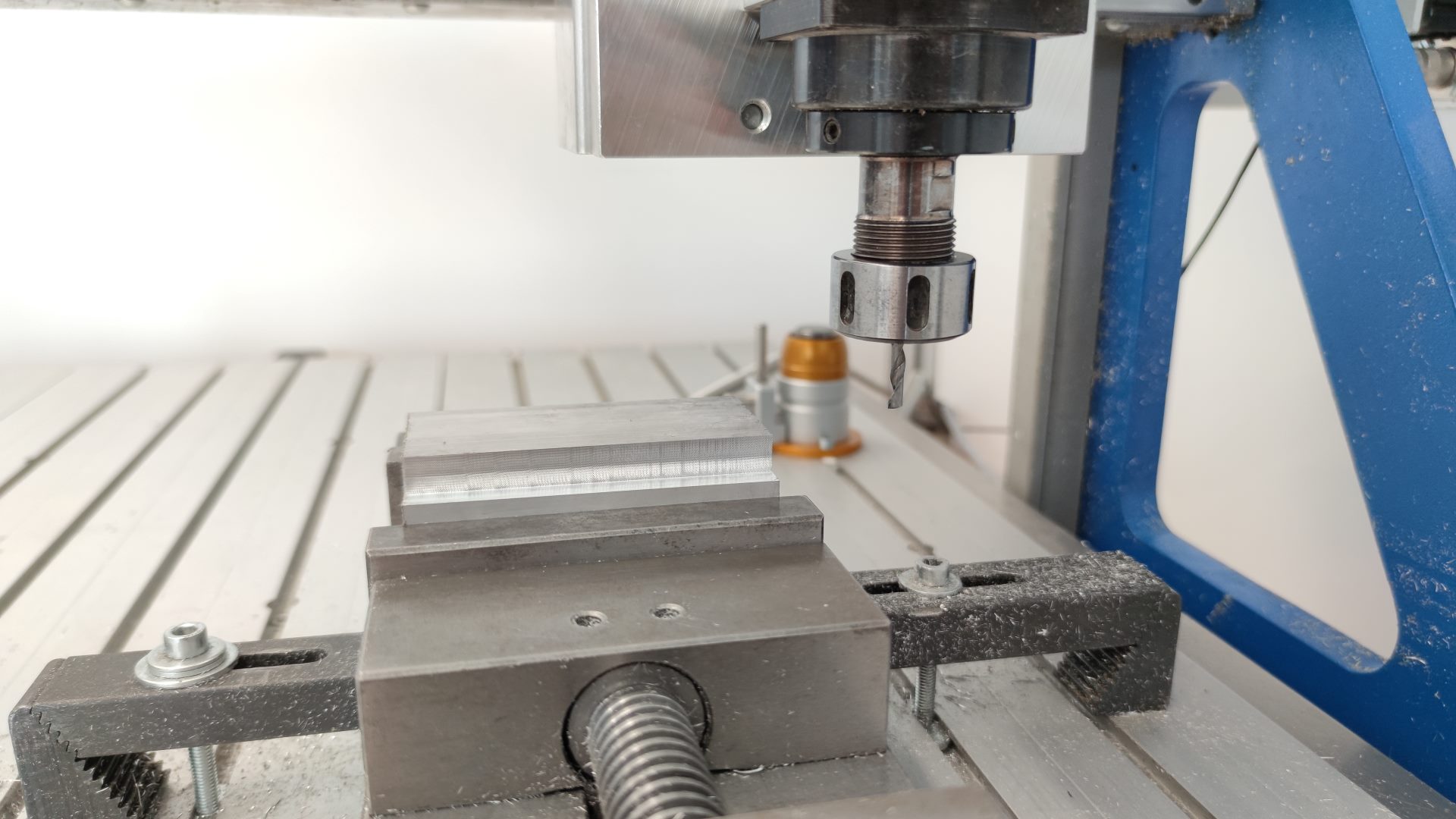
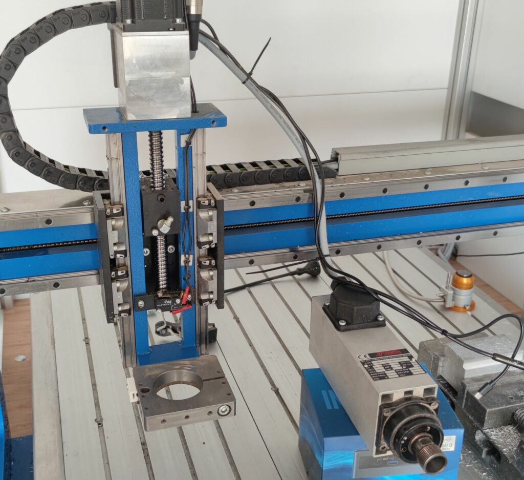
At our company we have a BZT 500 machine. It is a router style CNC machine with quite large work area. Router style CNC machines are especially known to have poor rigidity as it is traded for larger work area. Larger parts of the machine add to the lower stifness.
Our BZT machine did great and produced a lot of good parts, but we wanted to improve the performance further. When we were taking heavier cuts in aluminium we noticed a lot of vibration. We also noticed that the Z axis had a big overhang that was not neccessary and was causing problems.
Modifications on our machine
We decided to modify the Z axis of the machine since it was very easy, quick and cheap. The Z axis originaly had a clamp for the spindle but it only clamped spindle at the spindle nose with the width of the clamp of around 10mm. Also the clamp was mounted with big overhand and only mounted perpendicular with two screws. That is big mechanical disadvantage and design is significantly less rigid than it could be.
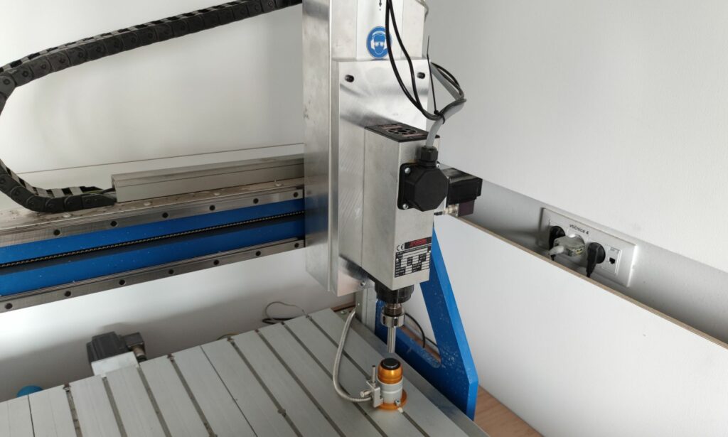
Our solution was very simple, since the Z axis already had flat surface at the upper side of the axis that was coplanar with the original spindle mount. That meant that the plate of aluminium could be bolted in at the top and also at the bottom to improve rigidity of the whole axis.
The spindle also had another way of mounting beside the bottom clamp. The back of the spindle was milled flat and already had four M6 screw holes for mounting. That way spindle had contact with the axis along whole length not only on the 10mm ring at the bottom as before. Mounting it that way significantly improved rigidity as well.
Did CNC upgrade work? CNC chatter results
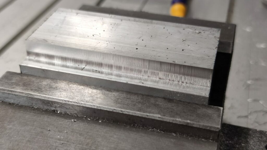
After making an upgrade, we had to measure results somehow. Vibrations are not simple to measure and cut performance can not be observed simply by eye. The simplest way of quantifying the performance after the upgrade was to observe chips with constant cut parameters as well as the surface finish. Of course, we had to perform the tests before and after the upgrade, so it was important that we did the tests before we started the upgrade and saved the test parameters.
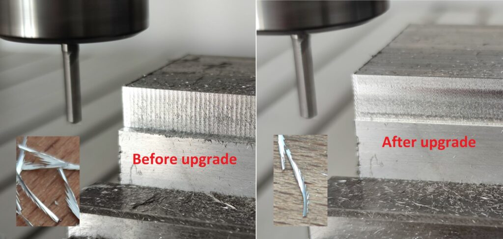
Chatter is also clearly visible from shape of chips that the cut produces. In picture above, shape of chips clearly indicates that excessive amount of chatter was present at the cut before the upgrade and small amounts are still visible after the upgrade.
The axial depth of cut (ADOC) was 10mm in all cases and was constant as well as spindle speed at 14000 RPM. The parameters that we changed were feed rate and radial depth of cut (RDOC) from 0.1mm to 0.5mm. The feed rate was ranging between 500mm/min to 1000mm/min.
Backlash compensation
Backlash can play a major role in chatter. The looseness in the axis means lack of rigidity and with the forces of the cutting the axis can start to resonate and cause chatter. With our PoKeys software or with Mach4 it is possible to eliminate backlash for improved accuracy but backlash mechanically still exists. So it is essential to eliminate backlash as much as possible with mechanical improvements to get better cutting results. To find out how it all ties together read our backlash compensation explanation blog post.
Other CNC upgrades
We noticed that spending time not only machining and making parts but also to improve CNC machine adds greatly to the user comfort and quality of the parts. Two of the recent upgrades we did was adding probe functionality as well as tool setter to measure tool lengths.
Mach4 probing enables to quickly locate parts on the table of the CNC machine to reliably machine features and to properly set the zero point. It also enables to measure features that you already machined or to detect for broken tools before you continue to machine with next tool.
We also later added cnc tool setter that saves us a lot of time when changing tools manually. We currently do not have ATC spindle so we have to manually change every tool. When tool is changed, the machine does not know its length so we previously had to manually touch off tools every time which took a lot of time.
In order to automate that process at least a bit we first touch off tool, then we set the part zero with the tool that is already touched off. When we change tool, we touch it off with the routine that is described in the blog and all is set and ready to go.
Sources:
1 – CNC chatter
2 – What causes CNC chatter
Related Posts