USB oscilloscope performance properties
USB oscilloscope performance properties are very important when buying USB oscilloscope. They can vary from vendor to vendor and from model to model. Let’s have a look a the most important ones which need to be taken into account when deciding about your new oscilloscope.
Channels
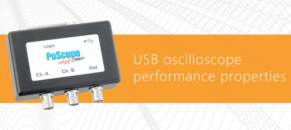
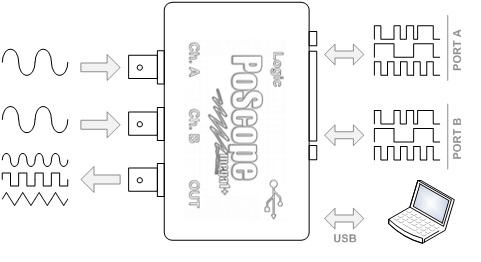
A channel refers to an independent input to the oscilloscope. The number of oscilloscope channels varies. Most commonly, they have two or four channels. The type of signal a channel carries also varies. Some oscilloscopes have purely analog channels (these instruments are called DSOs – digital signal oscilloscopes). Others, called mixed signal oscilloscopes (MSOs), have a mixture of analog and digital channels. All channels shlould have good range, linearity, gain accuracy, flatness and resistance to static discharge. PoScopeMega1 USB oscilloscope has two analog channels and 16 digital channels. Additionaly it provides third analog channel for generating analog signal (output). Digital channels are bi-directional.
Bandwidth
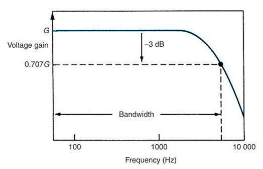
The bandwidth specification (sine wave) tells you the frequency range the oscilloscope accurately measures. As signal frequency increases, the capability of the oscilloscope to accurately respond decreases. By convention, the bandwidth tells you the frequency at which the displayed signal reduces to 70.7% of the applied sine wave signal. (This 70.7% point is referred to as the “–3 dB point” – a term based on a logarithmic scale.)
Most typical users choose an oscilloscope to display and measure complex signal, seen as a graph of signal amplitude over a time. Bandwidth is defined in the frequency domain, not the time domain. Complex signals, according to mathematics theory, can contain many spectral (sine wave) components. For digital signals – square signals, oscilloscopes must capture the fundamental, third and fifth harmonics or the display will lose key features. The bandwidth of the scope together with the probe should similarly be at least 3 to 5 times the maximum signal bandwidth for better than +/-2% measurement error.
Sample rate
Sampling is the process of converting a portion of an input signal into a number of discrete electrical values for the purpose of storage, processing and/or display. The magnitude of each sampled point is equal to the amplitude of the input signal at the instant in time in which the signal is sampled.
Sampling is like taking snapshots. Each snapshot corresponds to a specific point in time on the waveform. These snapshots can then be arranged in the appropriate order in time so as to reconstruct the input signal. In a digital oscilloscope, an array of sampled points is reconstructed on a display with the measured amplitude on the vertical axis and time on the horizontal axis.
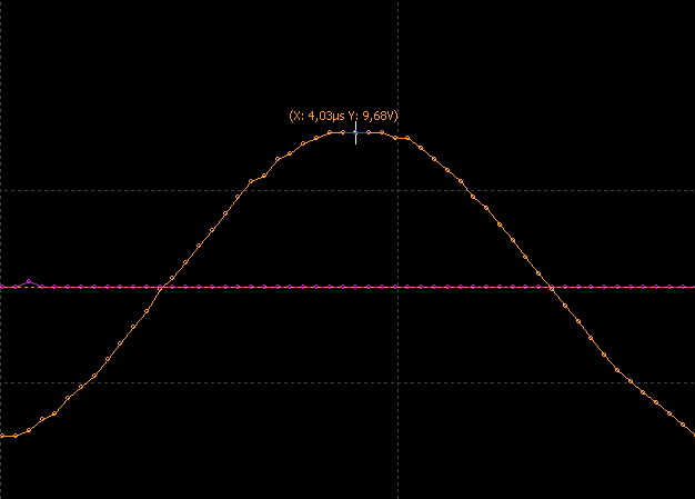
The sample rate of an oscilloscope is the number of samples the oscilloscope can acquire per second. As mentioned before it is recommended that your oscilloscope have a sample rate that is at least 2.5 times greater than it’s bandwidth. However, ideally the sample rate should be 3 times the bandwidth or greater.
ADC vertical resolution
Vertical resolution is a metric of the accuracy with which the ADC converts analog voltage to digital bits. For example, an 8-bit ADC converts a signal to 256 discrete voltage levels that are distributed across the selected “volts per division” setting. With 1 mV/division, the least significant bit is 39 uV. This is different from effective number of bits as it does not account for non-ideal characteristics within the ADC and the front end of the oscilloscope.
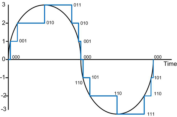
PoScopeMega1 has 12-bit vertical resolution which can be switched to 8-bit. Reason for decreasing resolution is explained under next section (Memory depth).
Connectivity and memory depth
Digital oscilloscopes use ADC (analog to digital converter) to digitize input waveform. Digitized data is then stored in the oscilloscope’s memory. Memory depth refers to exactly how many samples can be stored.
The connectivity of an oscilloscope delivers advanced analysis capabilities and simplifies the documentation and sharing of results. Standard interfaces (GPIB, RS-232, USB, Ethernet) and network communication modules enable some oscilloscopes to deliver a vast array of functionality and control.
Some oscilloscope’s connectivity enables only post-measurement transfer of data while for other such as USB oscilloscope PoScopeMega1 represents major link between the device and personal computer. In case of USB oscilloscope as external hardware of personal computer memory depth plays major role.
As the name suggests USB connectivity enables to transfer samples from oscilloscope’s memory to personal computer via USB. Those samples are transferred to computer at some transfer rate dictated by host computer and bus bandwidth. We already know that sample rate is speed at which samples of input signal are collected and stored to memory. Now we also have a transfer rate which reads memory and transfers data to computer. Memory serves as a FIFO buffer where first data comes in and first comes out in our case data from ADC converter comes into memory and data from memory goes to PC. Memory depth on the computer side nowdays is not a question anymore while you can always upgrade it easily and for low costs.
Ideal example would be to have a device with unlimited transfer speed and unlimited amount of memory. But in real world there are always a compromises. Usually microcontroller can operate at high speed thus sample rate can be really high but on the other hand USB doesn’t offer enough bandwidth to transfer all data or device doesn’t have enough memory for all samples.
According to that we can have two regimes of operation. One is direct streaming or as we call it PIPE mode and the other is BUFFER mode.
PIPE mode is a normal operation of device. Samples are collected at sample rate which is lower than transfer rate. In that case all collected data is transferred from device to computer uninterruptedly in a data stream.
BUFFER MODE is a special operation of device. Samples are collected at sample rate which is higher than transfer rate. Because of limited amount of memory only that data can be transferred to computer as data image thus having breaks between those data images. Sampling starts and when memory is full sampling is stopped until data already present in memory is not transferred to computer.
PIPE mode limit on PoScopeMega1 device is set dynamically, depending on resources used:
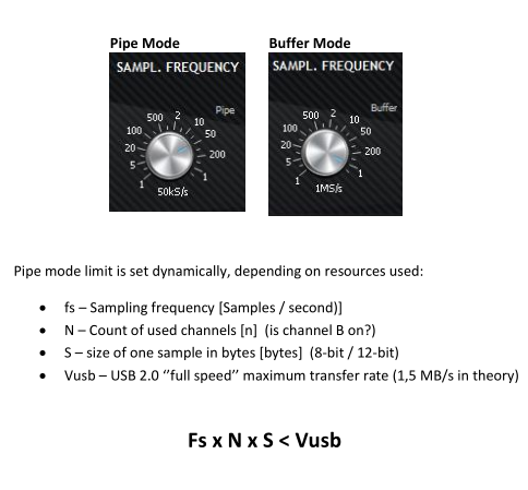
PoScopeMega1 maximum pipe mode sampling frequency is:
- 12 bit mode and two channels: 200kS/s,
- 8 bit mode and two channels: 200kS/s,
- 12 bit mode and single channel: 500kS/s,
- 8 bit mode and single channel: 500kS/s.
When Channel B is turned off, the Mega1+ maximum buffer mode sampling frequency is 2,5MS/s (single channel only).
Additional features
Features are part of software package or hardware itself. In case of PoScope4 software we offer free upgrades including all new features. Additionally many new features are results of great communication and feedback from our customers. Therefore many customer’s wishes become new features.
On the hardware side we try to design the best device with many useful features at a glance. PoScopeMega1 is USB oscilloscope with lowest power consumption on the market and not to forget to mention you get oscilloscope, logic analyzer and analog signal generator in one package.
Summary
As we can see there are some basic USB oscilloscope performance properties which needs to be taken into account anytime when you need to use or buy USB oscilloscope. Those properties also tells you if your current USB oscilloscope will be able to handle your needs and if you consider buying better one.
More informations about oscilloscopes cam be found here.
Please check some our products:
- Stepper motor driver-complete explanation
- USB CNC CONTROLLER-PoKeys57CNC
- Homing sensor-PoHome1IRNPN
- Bipolar stepper motor driver-PoStep25-256
- PCB tester- PoStep25-256

