PoScopeMega1+ as signal generator
Remark: There are two versions of PoscopeMega1. The older one has no signal generator and only two BNC connectors. The new one named PoScopeMega1+ has third additional BNC connector dedicated to signal generator. This article describes newer version PoScopeMega1+ which is also available in our store here.
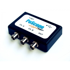
Although PoScopeMega1+ is by definition and implementation USB oscilloscope it offers one more additional and priceless feature – Signal generator. Having USB oscilloscope with capability of generating signals extends it’s usabillty to completely new dimensions. Let’s have a look.
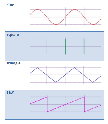
Signal generator is capable of generating different types of periodic signals with maximum frequency of 12,5kHz. Generated digital signal representation is converted with 16bit DAC to analog output signal. Possible shapes of signals are sine, square, triangle and saw, showed on images below. Signal generator can be used in a process of development, test and repair of electronic equipment, e.g. it can be a signal source (a reference signal) to test amplifiers.
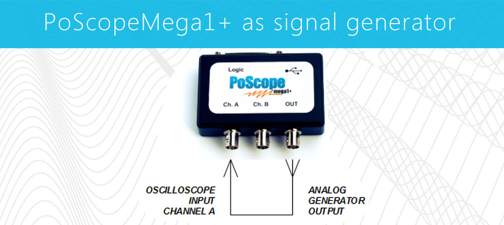
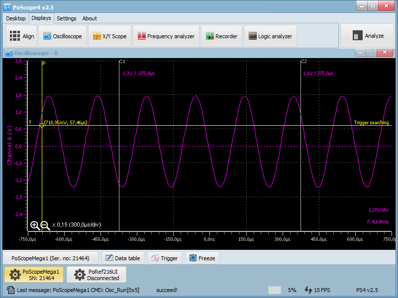
To show you the basic use of function generator, we connected analog input and analog output of Mega 1+. We made a loop-back of the signal and set up the generator to generate sine wave with frequency of 5kHz.

Open the plugin by clicking its icon in device buttons area of the PoScope4 software. To use signal generator on Mega1+ make sure you switch the device to analog DAQ mode first.

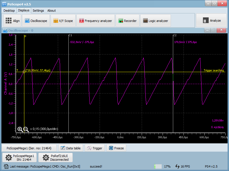
Find the signal generator controls on the right half of the PoScopeMega1+ control GUI. Besides shape of the signal (sine, square, triangle, saw) and its frequency (limited to max. 12.5 kHz) you can also set it’s amplitude, expressed in % of possible maximum output signal amplitude of 3.3Vpp. Below are screenshots of generated signals and captured back with Mega1+.


Please check some of our products:
- Stepper motor driver
- Stepper motor driver-complete explanation
- Homing sensor-PoHome1IRNPN
- Bipolar stepper motor driver-PoStep 25-256
- PCB tester

