Some users asked us to implement the support RC simulator interface, that would decode the data from a general purpose R/C (remote control) receiver in order to control outputs of the PoKeys device and/or allow the PoKeys device to be used as RC simulator interface. Allow us to present how easy is to use PPM sum signal decoding functionality, built-into PoKeys57 series devices.
R/C PPM sum signal
R/C systems for model planes, ships, cars etc. transmit the signal from the hand-held operator device (R/C transmitter) to a receiver, attached to a model (R/C receiver). To allow a good control over the model, multiple commands (servo channels) must be controlled at the same time – some systems support 3, 4, 6 or even 8 (or more) servo channels. This allows the model airplane pilot to control airplane’s elevator, rudder, ailerons, flaps, landing gear, airbrakes, lights etc. Each servo channel controlled the attached servo motors by the use of the PWM (pulse-width-modulated) signal, where the width of the periodically occuring pulses defines the servo arm position.
Before the rise of the digital transmission schemes in R/C transmitter and receivers, data for all servo channels had to be transmitter over a single wireless link, requiring all servo channel signals to be joined into one stream of pulses using PPM (pulse-position-modulation). Transmitter would encode the servo channel signals into PPM sum signal, then send it over wireless link. R/C receiver would then receive this stream of pulses and decode it by splitting it into the multiple servo channels (see the illustration below).
The rise of the PPM sum signal usage was advocated by the autopilot systems that appeared in mass market about 2010. When using autopilot system, the R/C pilot is not controlling the aircraft control surfaces directly, but via a processing system of a autopilot. Signals from the receiver must therefore be router first to autopilot and then to different servo motors on a model. Wiring between the R/C receiver and the autopilot box is much simplified if only PPM sum signal is connected, allowing the autopilot software to decode information of all servo channels at once.
Even though digital R/C systems are now predominantly used in the R/C hobby, the same PWM signals are used to control the servo motors on models. Multiple digital R/C receivers therefore support outputting of PPM sum signal in order to be used with systems, that can decode and use it.
Decoding R/C PPM data with PoKeys device – RC simulator interface
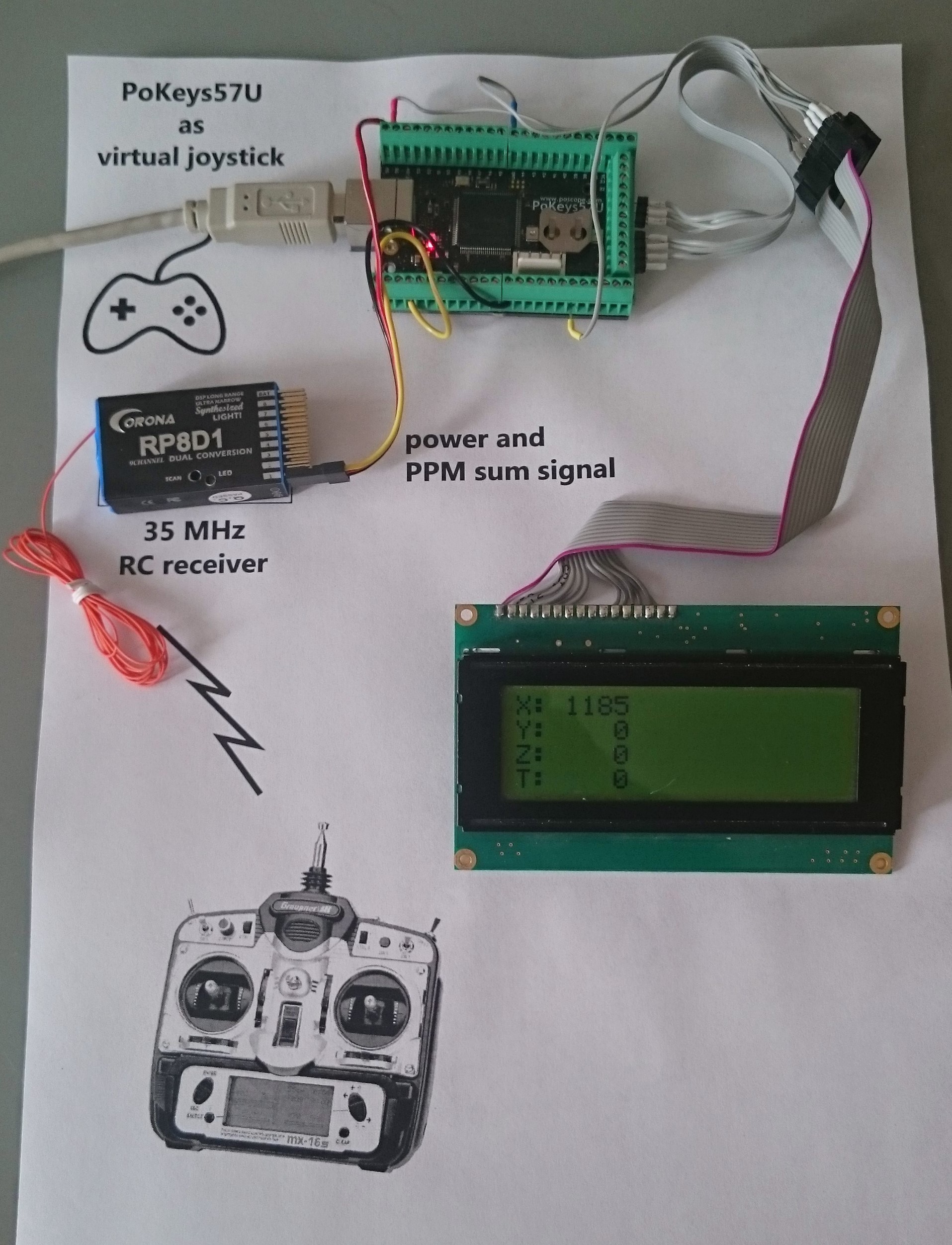
PoKeys57U USB I/O controller and PoKeys57E devices are capable of decoding the PPM sum signals, then use this information in PoBlocks. In this example, we will take a look on how this can be used to fly a model airplane in a computer simulation environment using the standard R/C equipment, making PoKeys a very capable RC simulator interface.
Preparing the receiver
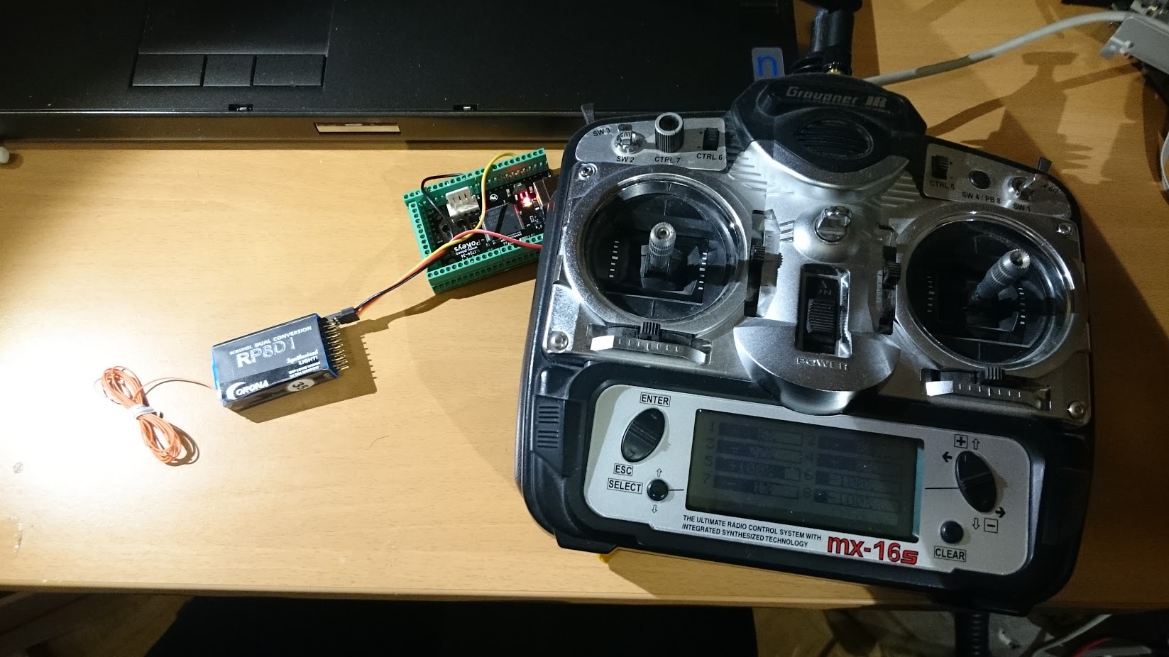
The receiver we had laying around did not officially support PPM sum output signal. Nevertheless, the signal was found in one of the internal signals and routed out instead of servo channel 1. If one uses a receiver that already supports PPM sum signal, this step can be omitted.

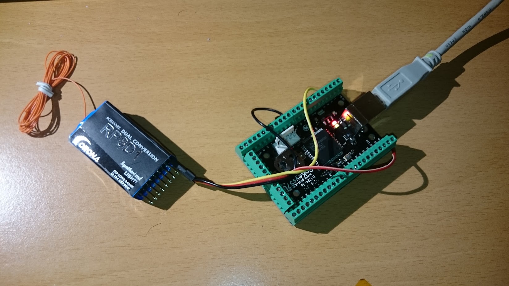
Connecting the R/C receiver and PoKeys device
The connection between PoKeys57U (or PoKeys57E Ethernet I/O controller) device is simple – connect receiver’s ground to PoKeys’s GND pin, receiver’s power supply to PoKeys’s 5 V pin and the PPM sum signal to pin 3 (PoKeys57U) or pin 24 (PoKeys57E).
Enabling the PPC decoder in PoKeys device
Activate the R/C transmitter and open PoKeys configuration software. Under Peripherals > PPM decoder, PPM decoder can be enabled in PoKeys device. The progress bars display received signals, in this case, all 8 channels are active.
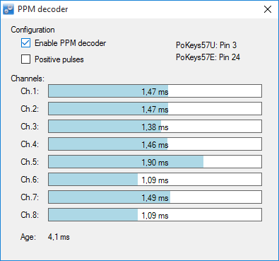
The following image shows the status of RC transmitter’s outputs. It can be seen that the signals are correctly decoded:
-100 % on the transmitter equals to 1.09 ms wide servo channel pulse
+100 % on the transmitter equals to 1.9 ms wide servo channel pulse
0 % on the transmitter equals to 1.47 ms wide servo channel pulse
Using the decoded PPM data
Now, the decoded PPM data can be imported into PoBlocks, processed, then exported as USB Joystick data. In the example, we’ll also display the axes values on the LCD screen.
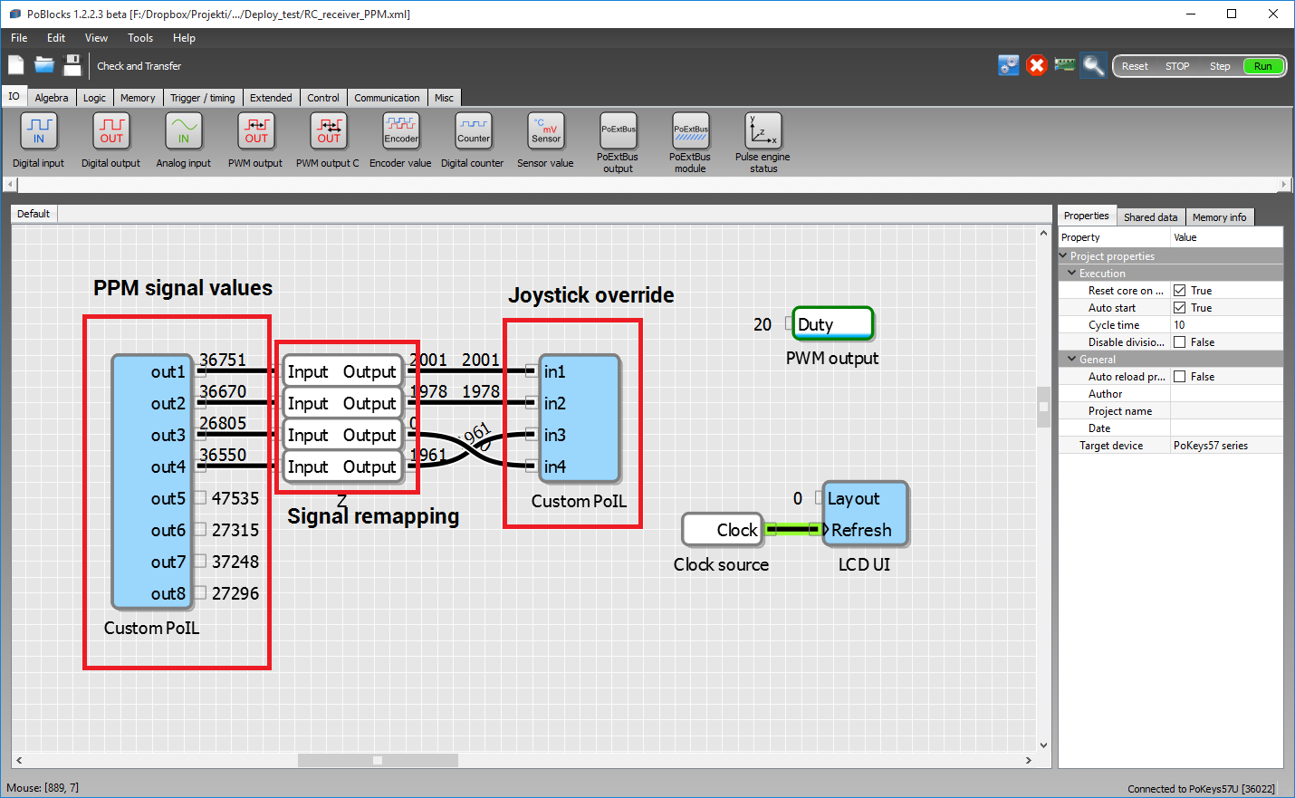
The example project contains three important sections – import of PPM signal values, signal remapping and joystick override. There is also a PWM output block for setting the LCD display contrast voltage and LCD UI block for displaying the received data.
Download PoBlocks example: RC_receiver_PPM.xml
PPM signal values
PPM signal values are imported into PoBlocks using the Custom PoIL code block. Code can be edited by double-clicking on the blue block:
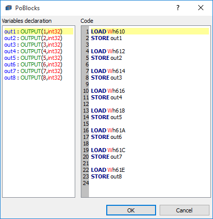
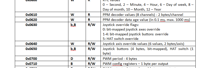
The left side defines the inputs and outputs of the PoIL block. In this case, we have eight 32-bit outputs. On the right side, the PoIL code of the block is given. In this example, the values are copied from PPM decoder registers to block outputs. The register addresses are given in the PoIL.pdf document (in PoKeys installation folder) under memory organisation topic (the table below is from that manual). PPM decoder values start at address 0x0610, are word-type (16-bit signed integer) and are read-only. To read the register, LOAD Wh610 command is used – LOAD instruction loads the working register with the value given by the operand. Operand Wh610 indicates that this is a Word (16-bit) register at hexadecimal address of 610 (0x0610). The STORE out1 in the next line stores the value to the output port of the block.
Signal remapping
PPM signal is decoded into multiple channels of PWM servo signals. Each decoder channel’s value indicates a width of the pulse, given in 40 ns (nanosecond) units (default high-resolution time unit in PoKeys devices). The neutral servo state (center) is usually defined by a pulse width of 1.5 ms (millisecond) – in terms of PPM decoder values, it has the value of 1,5 ms / 0.00004 = 37 500.
In order to make sense of these values, the signal rescaling block is used to remap the values from the [27000 – 47000] interval to [0 – 4095], which can be directly fed to PC as 12-bit joystick data.
Joystick override
Another PoIL block is used to present the decoded and remapped PPM signal data as USB joystick axes movement. PoKeys57U device represents itself as multi-axes USB joystick device with each axis having 12-bit resolution (this is why we had to remap the signals in the previous step). By default, joystick is configured in PoKeys configuration application, where analog inputs of the PoKeys device can be mapped to individual joystick axes.
However, in this example, PPM signal data should be used to set the USB joystick axes values. As can be seen in the registers table above, registers 0x0630-0x0635 contain joystick override flags. These are registers that can be accessed as a Byte or bit register. Register at address 0x0630 contains bit-mapped joystick axes override flags. To override the axes 2 (x-axis), 3 (y-axis), 4 (z-axis) and 5 (throttle), bits 2-5 must be set in this register. This is done by writing a hexadecimal value of 0x3C (00111100 in binary) to the register 0x0630 using the commands
LOAD DL[h3C] # Load literal hexadecimal value of 0x3C to working register
STORE Bh630  # Save the working register to 0x0630 joystick axis override flags register
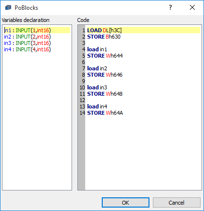
The block has 4 input declarations (hence displaying 4 input ports in PoBlocks). The in1 (first input) should be mapped to joystick’s x-axis. Since this is axis 2 of the PoKeys device, the value of input 1 must be saved to axis 2 register at address of 0x0644. Each value is of 16-bit word type, therefore 0x0640 is the address for the axis 0, while 0x0642 is the address for the axis 1. Similarly, values of inputs 2, 3 and 4 are mapped to registers 0x0646, 0x0648 and 0x064A, respectively.
Testing
Once the R/C transmitter is activated, PoKeys will start functioning as RC simulator interface, allowing the use of various PC simulators with the standard RC receiver. One can fly in the virtual environment with the same equipment as in reality, allowing the pilot to use the interface he/she is accustomed with.
However, the received PPM signals can also be additionally processed in PoBlocks, allowing the user to activate and control different loads with a remote control – the signals can be evaluated and used to drive digital outputs, PWM outputs etc. of the PoKeys device.
Here is a complete explanation of the stepper motor driver.
- Bipolar stepper motor driver-PoStep25-256
- Plasma voltage divider
- Plasma cutter troubleshooting guide
- 4th axis for CNC
Related Posts