Do you want to build DIY Mach4 laser cutter with PoKeys CNC controller? Read this post to find out how to configure the Mach4 as well as plugin and all the signals..
Components for DIY Mach4 Laser Cutter
Laser cutter is usually only 2 axis machine with gantry style layout. Contrast to CNC milling machines, laser cutters are lightweight machines with focus not on rigidity but on bigger cutting area. There is usually laser head and mirrors (in case of CO2 laser) mounted on gantry with very little weight.
The rigidity and proper design is on the other hand essential if you want precise positioning without vibration. The vibration can be visible on the laser-etched surface when path is changing direction.
Laser head options – CO2 lasers
Regarding the laser source, there are two main options with DIY CNC laser cutters. There are diode lasers and CO2 lasers. They each have advantages and disadvantages and there is no “best” option.
CO2 lasers use (big) glass tubes, filled with CO2 gas that produces beam of infrared laser light when excited. The wavelength of laser is around 10 micrometers. It is one of the most powerful continuous beam laser sources. The output power can be more that 100 watts of optical power. Beside the laser tube itself there is high voltage source that powers the laser tube.
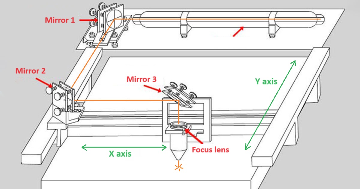
The advantage of CO2 lasers is their high output power and invisible wavelength that can cut through acrylic and other transparent materials. On the other hand, the laser tube is big and fragile and has to be properly mounted on the fixed part of the laser machine. The beam is then directed with special mirrors on the optical path to the laser head that has to focus the beam and direct it on to the material. There is a lot of optical elements, that has to be properly aligned and calibrated to ensure the best quality of cut.
The support equipment for the CO2 laser also includes the industrial water chiller, that has to circulate the water flow throug the laser tube in order to cool it. The air assist is also neccessary, otherwise optics will get damaged because of the smoke from cutting.
In conclusion, CO2 lasers are much more complex and need more support equipment compared to the diode laser sources.
Diode lasers
Other option is the diode laser source. It uses semiconductor as the laser source. The laser source is usually packed into the laser module with the driver circuitry on top of it. The cooling of the laser diode is managed by the module enclosure that is made from aluminium and has active colling with fan. The circuitry mainly consist of constant current driver that provides the laser diode with proper power and is in most cases already on the laser module itself.
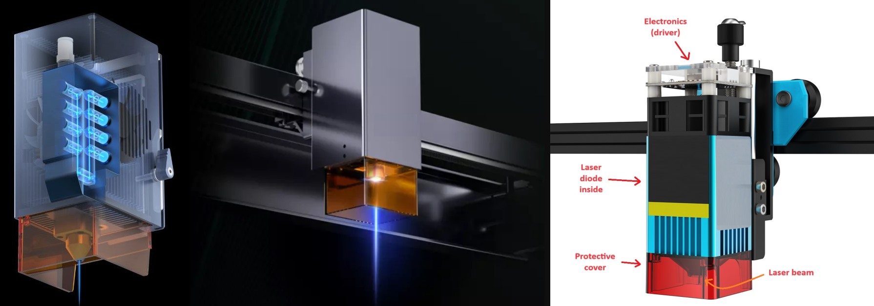
The output power of laser module can be several watts, up to 10-20 W. Nowadays, most of the diode laser modules come with multiple individual laser diodes packed in one module and focuser optics, that combine all of the beams into one beam. Inidividual laser diode can have around 5W power rating, but when combined, the module can have 20 W.
The big advantage of the diode lasers is the small form factor and price. They are usually much cheaper compared to the CO2 lasers especially when considering the fact that they don’t need support equipment. They have lower power consumption, but the output power is also much smaller than CO2 lasers. Diode lasers also have visible spectrum wavelength that can not cut through transparent materials like acrylic.
Diode lasers usually have much smaller spot size, that is diameter of the beam. With diode lasers, it can be as small as 0.08mm. On the other hand, you can be very happy if you achieve 0.3mm spot size with the CO2 laser. That difference also means that the power is much more concentrated with the diode lasers and they can be very effective at cutting.
Synchronization with motion for Mach3 & Mach4 laser
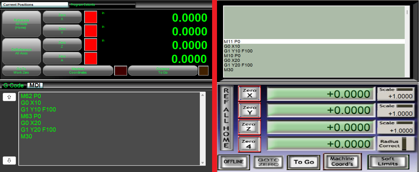
There are two modes of synchronizing the laser commands with motion. For ON/OFF synchronization the M62/M63 commands are implemented in Mach4. For Mach3 these commands are M10/M11. Normal M (macro) commands can have up to 500ms delay, which with lasers can cause burn-through or imprecise cutting. On the other hand, M62/M63 are synchronized with the next motion command, so they are turned on with precise timing.
The other option for synchronization is when you want to synchronize the PWM duty cycle (laser power) with motion. For that, some simple logic is required in our PoBlocks that enables that kind of synchronization, since it is not enabled by default with Mach4 laser. We will cover that in the future blog post.
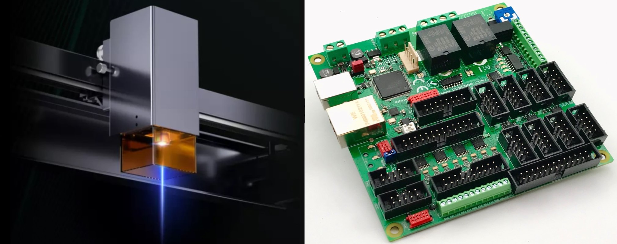
PoKeys and laser electronics
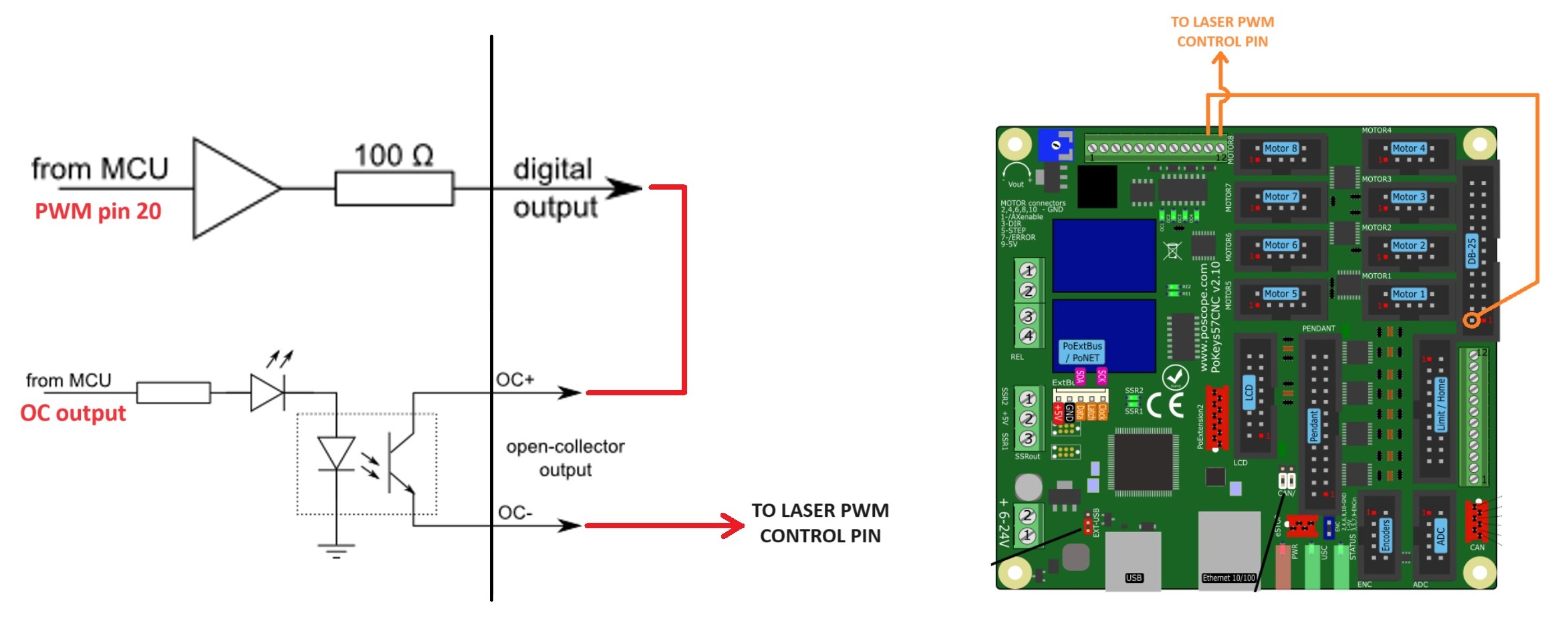
Controlling the laser is very simple. Both CO2 and diode lasers have their own power supply. There is usually only one signal necessary for controlling the laser. The signal is PWM type where duty cycle determines the laser power from 0% to 100%. If signal is at 0 V all the time, laser is disabled. It is recommended to use PoKeys pin 20 of PoKeys57CNC device (available on the side DB-25 connector) because it has 5 V output level and PWM capability, which is in most cases also recommended signal level for laser power supplies or modules.
Because there is no direct option to control the ON/OFF functionality as well as PWM duty cycle of the same signal, the PWM output has to be masked with OC output. In other words, you need to toggle the PWM signal on/off with another (digital) output. There are multiple OC (open collector) outputs available on the PoKeys57CNC and the following is a neat solution to easily combine PWM and on/off signals to control the laser.
Mach4 laser configuration
The M62/M63 (or M10/11 in Mach3) commands are used to synchronize specific output state with the motion commands. In Mach4, the output has to be selected in the Mach4 control configuration as shown below on left. Only the ON/OFF command is synchronized with motion via M62/63 and it controls the OC output.
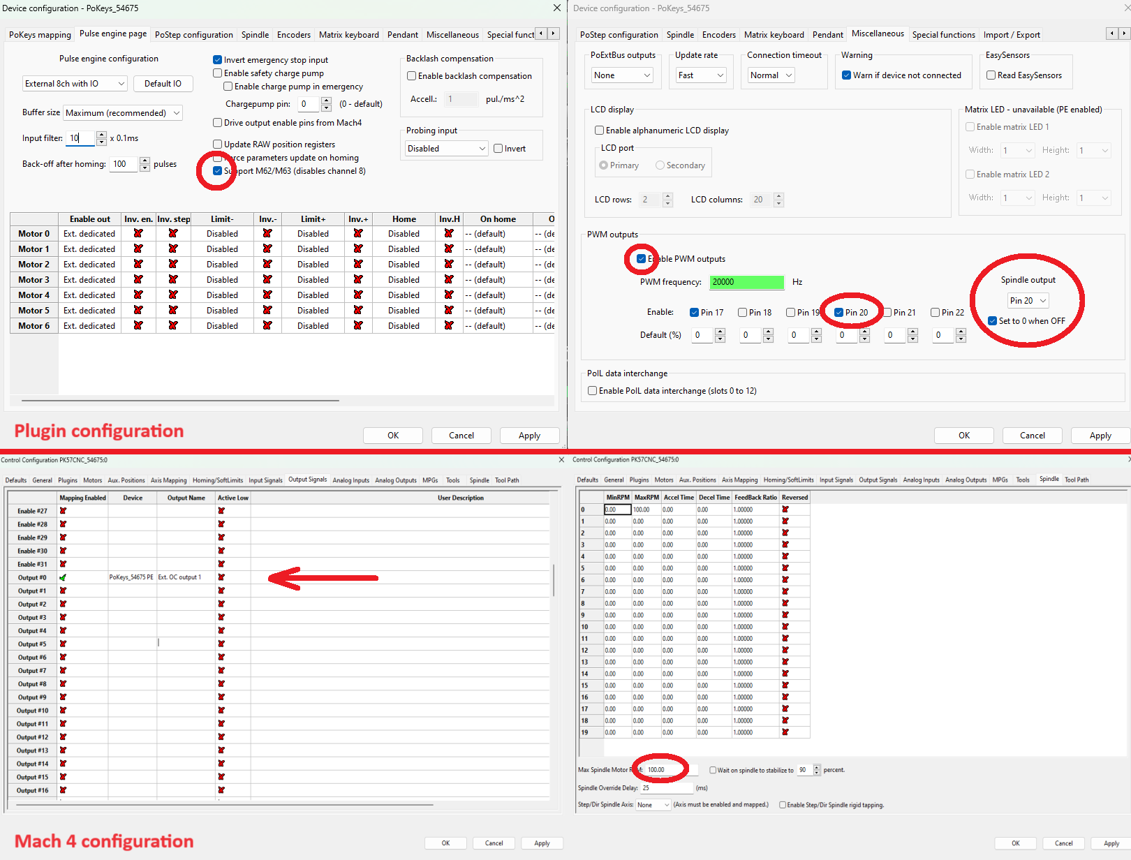
The spindle configuration in Mach4 is necessary for PWM functionality and control of the duty cycle. The max RPM of the spindle is set to 100 so that in the M3 Sxx command, “xx” is the direct percentage of the power (or percentage of the duty cycle). Using PWM for power control is optional and if the laser module does not support power modulation, PWM signal configuration can be omitted.
Mach3 configuration
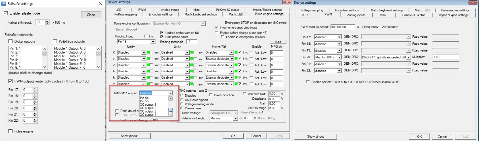
Before making a configuration in Mach3, there is failsafe setting, that has to be enabled in PoKeys application. Under “peripherals” choose “failsafe settings” and enable failsafe mode along with PWM outputs that you previously set to 0. The configuration has to be sent to controller. That way, the pin 20 (or any other) will be initialized with 0% duty cycle at the boot and your laser diode will not be turned ON mistakenly. A dedicated physical on/off switch (together with interlocking switches on the machine cover) is mandatory to allow safe operation of the machine.
In Mach3, the configuration for fast output control using M10/M11 is as follows. In the PoKeys plugin under Pulse engine settings, you can configure which pin is controlled with M10/M11. We suggest using one of the OC (open-collector) outputs for laser ON/OFF control. For laser power control, the preferred way is to use the spindle speed as laser power and connect spindle speed directly to PWM on pin 20 (shown below) that needs to be set as “Map to DRO in %”.
G-code commands
M62 Px command turns on an output “x” synchronized with the start of the next motion command. Similarly, M63 Px command turns that output off synchronized with next motion command. If no motion command is given, the output will not turn ON/OFF. That way the output is turned on, in our case the OC output. But for PWM functionality, you need to send the M3 Sxx comand with “xx” being the percentage of duty cycle (if max RPM is set at 100 for the spindle). For turning the PWM off at the end of cutting M5 command should be sent.
In Mach3, the synchronized ON/OFF commands are M10/M11. The M11 P0 commands turn the selected output ON while the M10 P0 command turns it OFF. It is essential to use P0 parameter to the M10/M11 gcode otherwise the output will not work properly. For both commands to take effect, subsequent motion command is required. PWM for power control is also turned ON/OFF with M3/M5 command similar to Mach4.
Useful tips
In some cases you might be running the CNC engraver or router and you would like to add laser diode along with the spindle. In that case we recommend that you create different Mach profile for running the laser with different pin mapping so that the spindle PWM output is connected to the different pin than the VFD and that pin controls the laser diode. Make sure to follow precautions in regards to installation of the manual laser enable switches in order to prevent unintended laser activation. You could also use our power mosfet adapter for turning on/off the power to the laser.
Alternatively to Mach3/Mach4, you can use software called Auggie, which was developed by the original Mach3 author Art Fenerty for PoKeys57CNC devices. It directly supports laser cutting and engraving with real-time power controller (depending on the actual feed rate).
There is also specialized G-Code generator for grayscale laser engraving using Mach4/PoKeys57CNC and M67 commands. The application is bundled with PyInstaller as a standalone executable, requiring no Python installation to run. Thanks to MoMo830 for creating it.
Related Posts