Logic analyzer is an electronic measurement instrument, capable of capturing and displaying multiple signals from a digital circuits. With this powerful tool you can observe many digital signals at the same time and perform exact time measurements. It is useful for various tasks in electronics design, testing and repair:
- analyze timing errors,
- verify timing diagrams,
- observe timing relationships among many signals,
- decode the information on buses,
- view state machine traces.
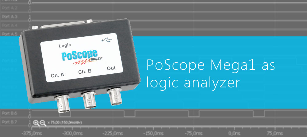
PoScopeMega1+ as logic analyzer
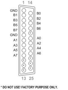
With PoScope Mega1+ you can simultaneously display, capture and analyze up to 16 digital channels varying from 0 to +5V. There are two ports (Port A and Port B) and each supports up to 8 signals. The pinout of DB25 connector from the back of the PoScopeMega1 is on the image below.
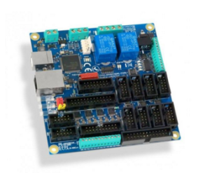
For this example we used our PoKeys I/O device. PoKeys is a powerful little device with extensive amount of functions. You can program it with easy-to-use graphic tool, the PoBlocks. We used PoProbe to tap into its outputs, also available in our web store.

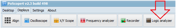
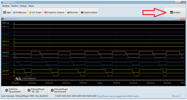
Open Logic Analyzer display by clicking its icon in the Displays tab of PoScope4 software:
Below you can see an example of displaying digital ports of a PoKeys input / output device. As in oscilloscope mode, you can click Analyze button to closely view the captured data.
When you’re in Analyze mode, use the yellow selector above to select the part of captured data for even closer observation. Resize the yellow selector with scroll wheel and drag it to the point of interest.
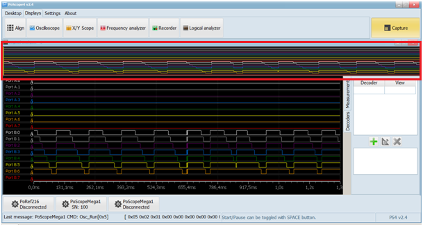
On the right side of the Logic analyzer display you will find 2 tabs. Under measurements you will find width, frequency, period and duty cycle. Values will change as you hover over the chart and signals.
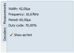
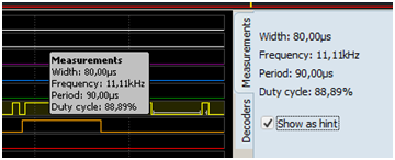
When done, you can hover mouse over the part of the certain waveform on the chart to see additional measurements.
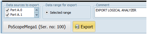
You can export the data selected in overview window to an external file in different data formats.
Additional information
If you’d like to read more about how to decode I2C protocol please click HERE.
Users can get more general informations about logic analyzers on link HERE.
More informations about USB oscilloscope PoScopeMega1.
Please check some our products:
- USB CNC Controller-PoKeys57CNC
- Stepper motor driver-complete explanation
- Homing sensor-PoHome1IRNPN
- Bipolar stepper motor driver – PoStep25-256
- PCB tester – PoStep25-256
Related Posts